The Expanding Frontier

Creating Sci-fi RPG Resources

  • Home
  • Order a Map
  • Order Miniatures
  • Supporters
  • About
  • Bio

Category Archives: 3D Models

UPF Destroyer Model and Ship Stands

This post is a couple of days late as I was traveling and completely forgot to get a post queued up for Tuesday.  And this is not what I had planned to post at all.  I had not planned to do another model post this month.  I was planning on putting together a table of all the star systems on the Extended Frontier Map to provide the spectral types of all the stars and notes about they systems. However, on my flight I had some time to kill and wasn’t completely decided on what I wanted to include in the table so I decided to do a bit of modeling.  I’ll probably finish up that table for next week.

The UPF Destroyer

Since I didn’t have my battleship mini or calipers with me, I couldn’t continue working on the battleship model. Instead, I thought I’d take a look at the UPF destroyer and start working on that.  Since there is no existing model for this ship, this would be a scratch build.  There are two references for this ship.  One in the Knight Hawks Campaign book on page 7 in the image showing the silhouettes of the various ships and the small game counters.

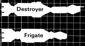
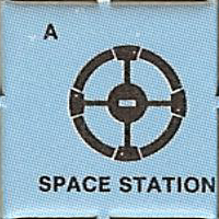
The silhouette images for both the frigate and destroyer are shown in the image to the right.  As you can see, the ships are fairly similar.  The destroyer is shown with a shorter engine block area, a longer neck, and an obvious gun on the bow.  The counters for the two ships are shown below.

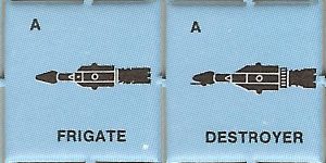
These images also show a slightly smaller engine area and noticeable gun on the bow, but here the neck area is about the same and the main fuselage is longer.  Also, the width of the fuselage is a bit larger on the destroyer.  Since there is some detail on the body of the ships in the counters, you can notice that the main body of the destroyer is very similar to the body of the frigate, mainly that it has that same cross structure.

Since it’s always been in the back of my mind to make a set of models that match the silhouettes in the book in the future, I chose to take the counter as my guide for this project.  Especially since that meant that I could use a lot of the work done for  the frigate on the destroyer.

Building the Model

The frigate is a HS 5 ship while the destroyer is a HS 6 ship so we expect in the end the destroyer will be a little larger.  I started by pulling up the model for the frigate.  Since I’m using the original mini model as the basis, this model, like my recreation models, are not designed at an exact model scale but at their actual physical size.
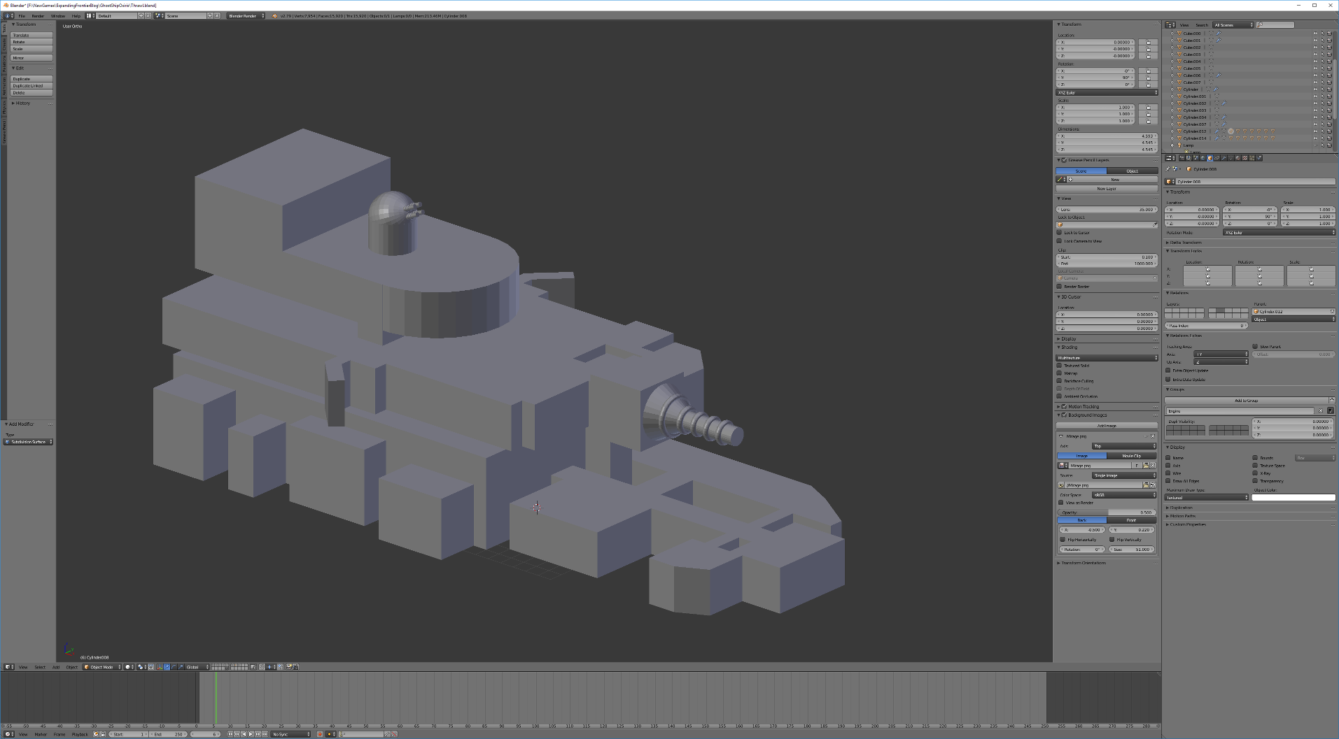
Main Fuselage

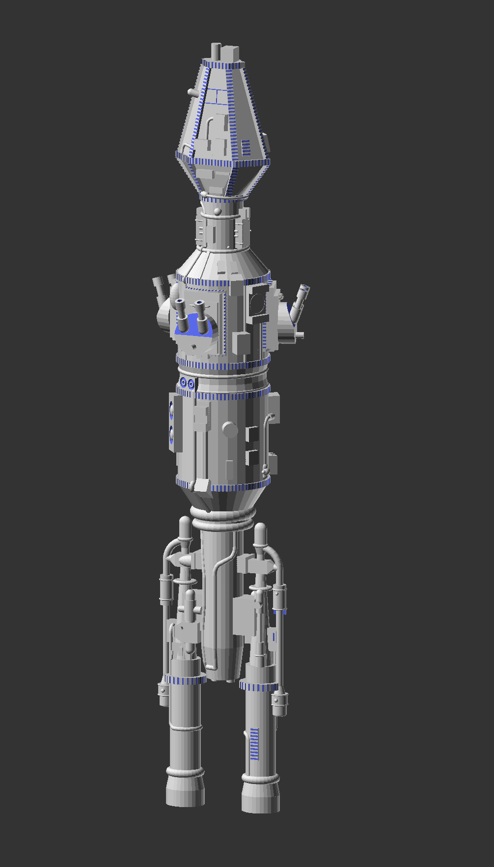
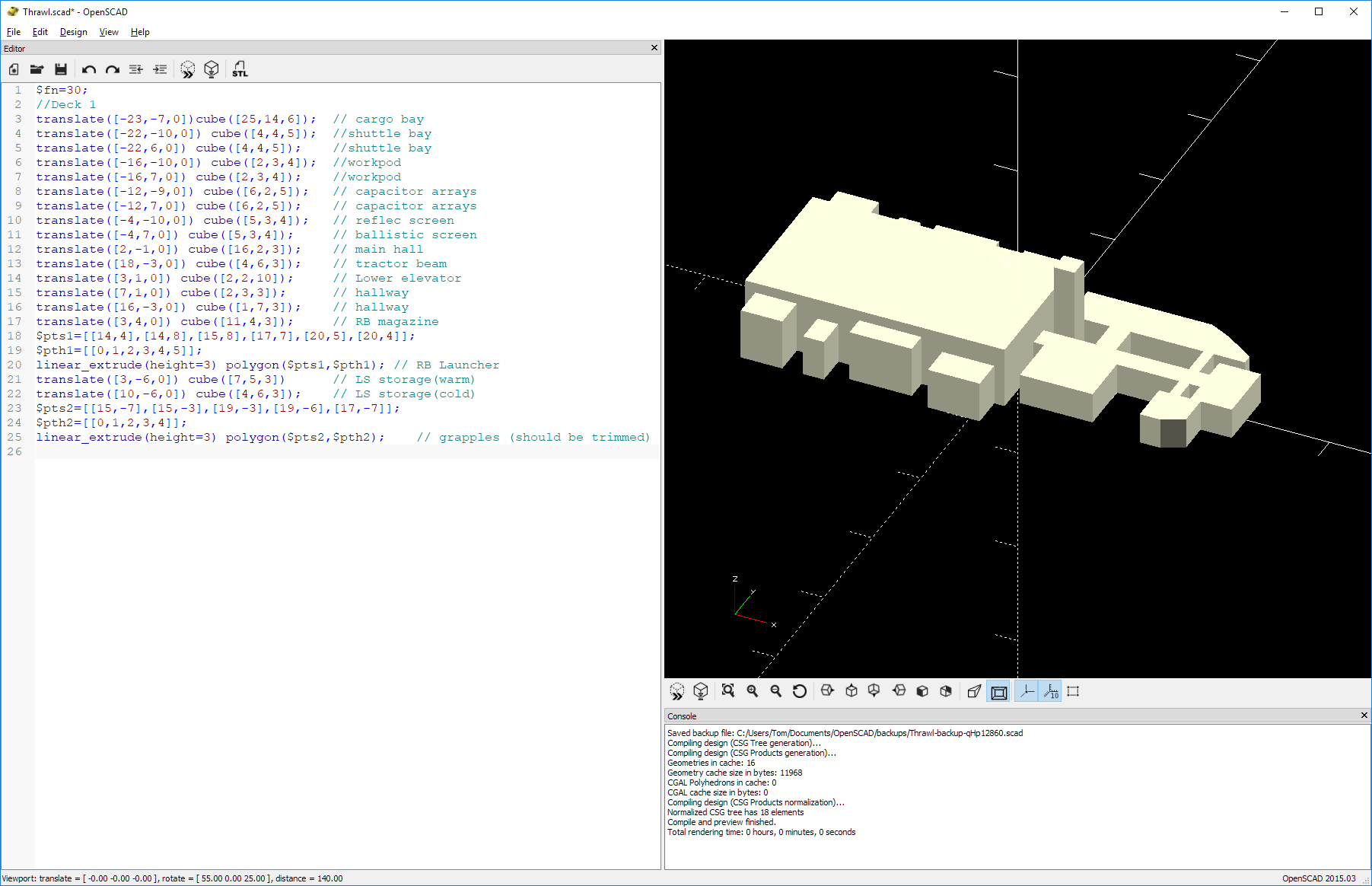
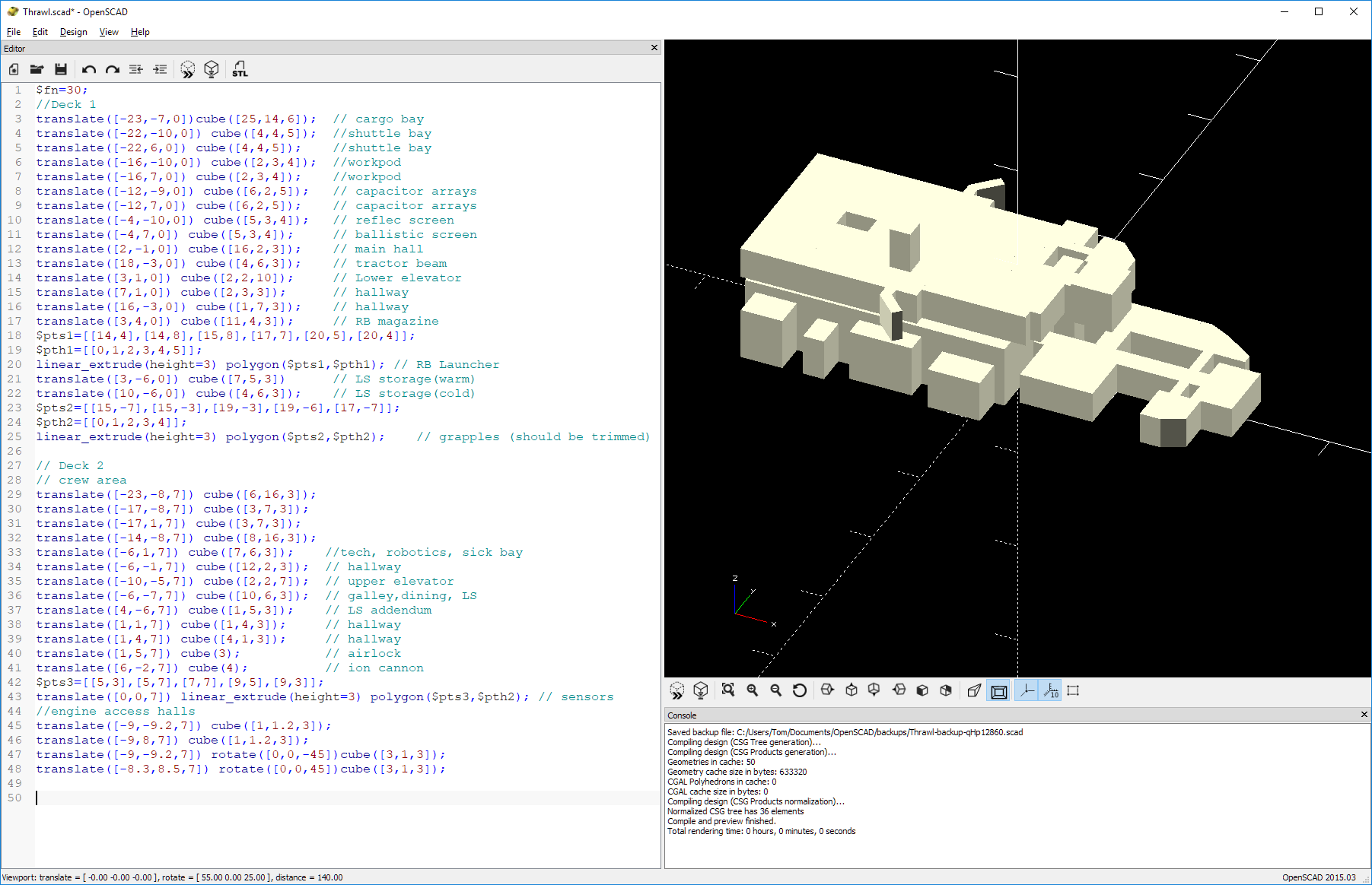
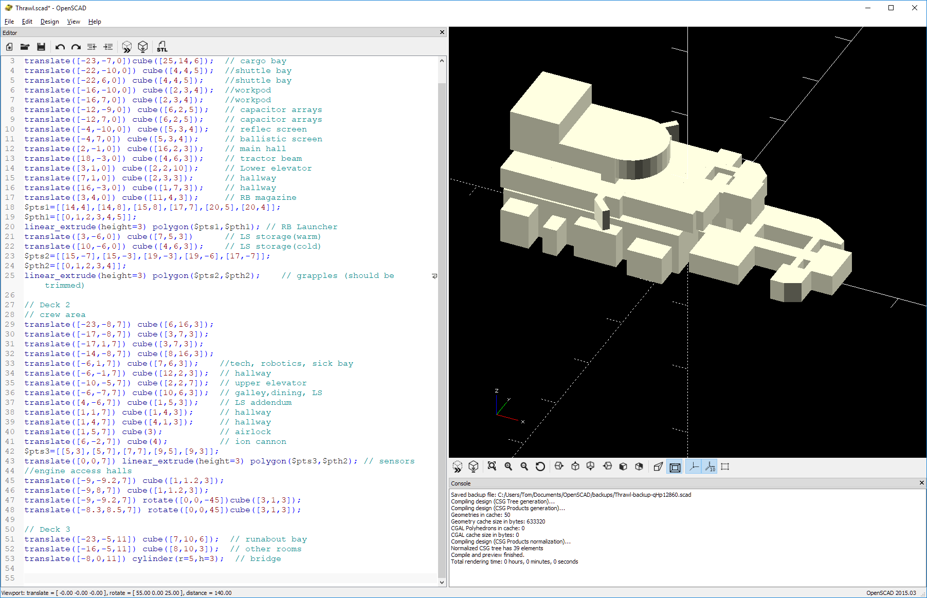
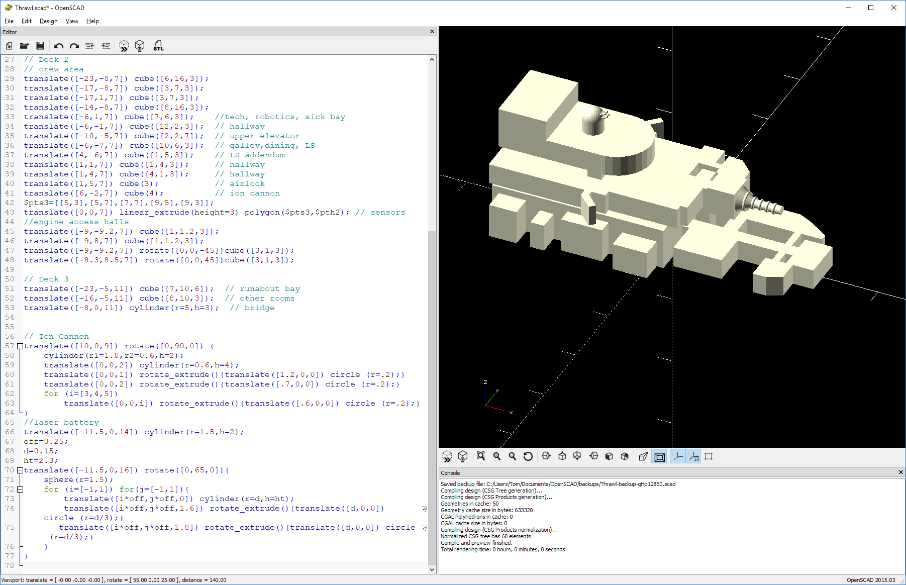
I’m doing this design work in OpenSCAD which looks and acts very much like a programming language.  I give it positions, sizes, and rotations of various primitive shapes and it places them on the model.  I then “compile” it to get a render.  For example, this is the code that draws the main body of the frigate with its crossed block structure:

cylinder(r=3,h=15);
for(i=[0,90]){ rotate([0,0,i]){
  translate([0,0,2]) cube([11,2.9,4],center=true);
  translate([0,0,7.75]) cube([11,2.9,6.5],center=true);
  translate([0,0,4]) cube([10.5,2.5,1],center=true);
  translate([0,0,11]) scale([1,1,1.4]) rotate([0,45,0]) cube([7.77,2.9,7.77],center=true);
  translate([5.5,0,8]) sphere(r=1);
  translate([-5.5,0,8]) sphere(r=1);
}

Since I wanted that same block structure for the destroyer, just bigger, I just needed to increase the length and width of the blocks and shift the positions of some of them to make the body longer.  Basically, I just change a few numbers and re-render.  If I wanted to just make it bigger everywhere, I could wrap all of that in a scale() command and not change anything.  However, I wanted to keep the core diameter (that first cylinder) the same size so I modified each of the items.  Overall, I increased the length of this part of the ship by 2.6 mm and its width by 3 mm.

I kept the neck length nearly the same but stretched out the spherical section of the upper body by 0.3 mm (10%).

I also lengthened slightly the area behind the crossed block structure.  In the counter image, this is larger on the destroyer than the frigate and has a grilled structure, so I added in a hull section to match that image.  This also helped to lengthen the entire body of the ship.

The Bow

For the “head” or bow of the ship, I decided to just reuse wholesale the head of the frigate model.  I figure that since the ships are nearly the same size, the designers would just reuse an existing design to save on design and fabrication costs.  However, I did make one change.  On the frigate, the main gun extends out from the center of the head which means that the long lasing cavity of the laser cannon runs through the center of the bow taking up space inside the ship. 

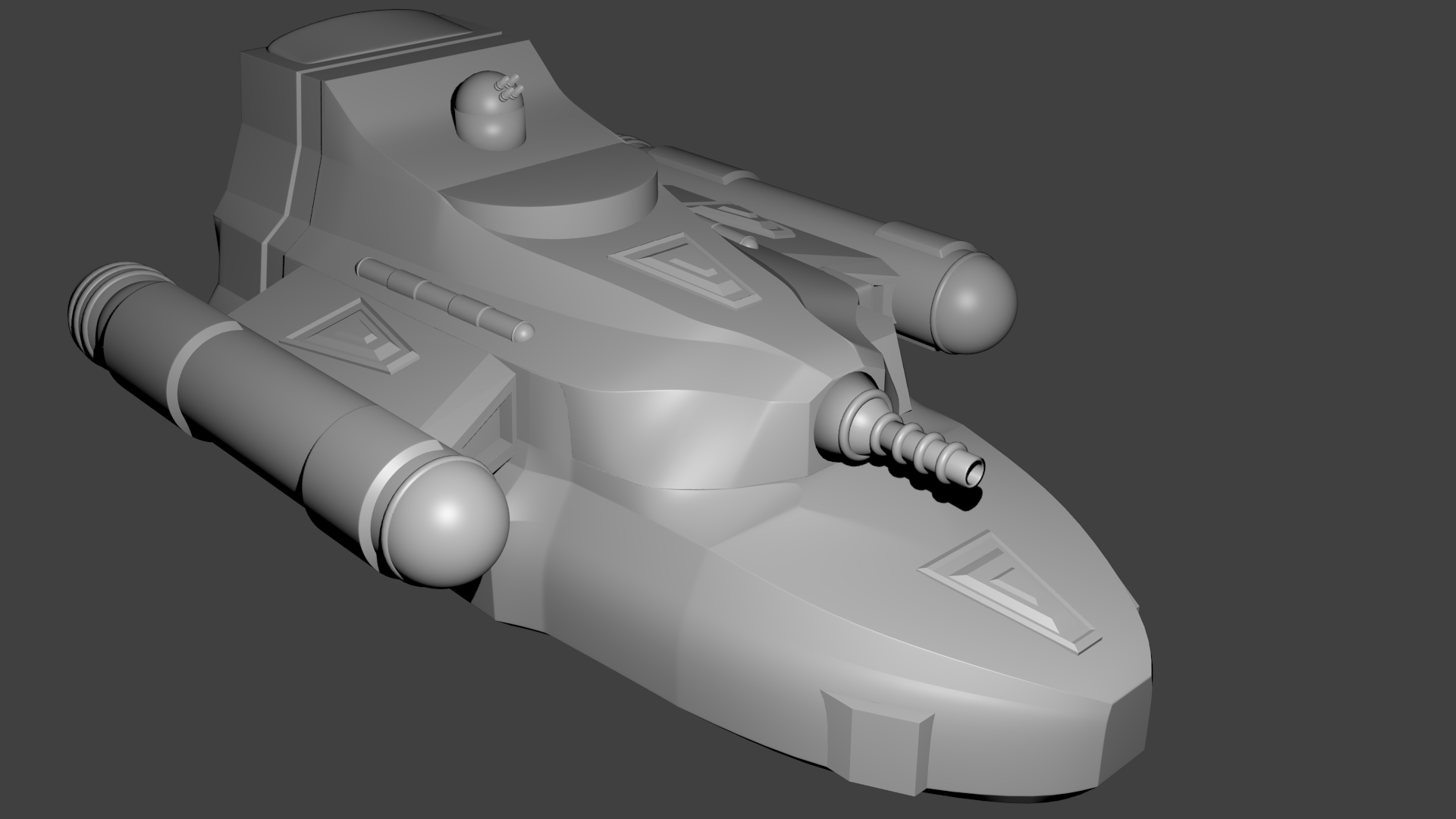
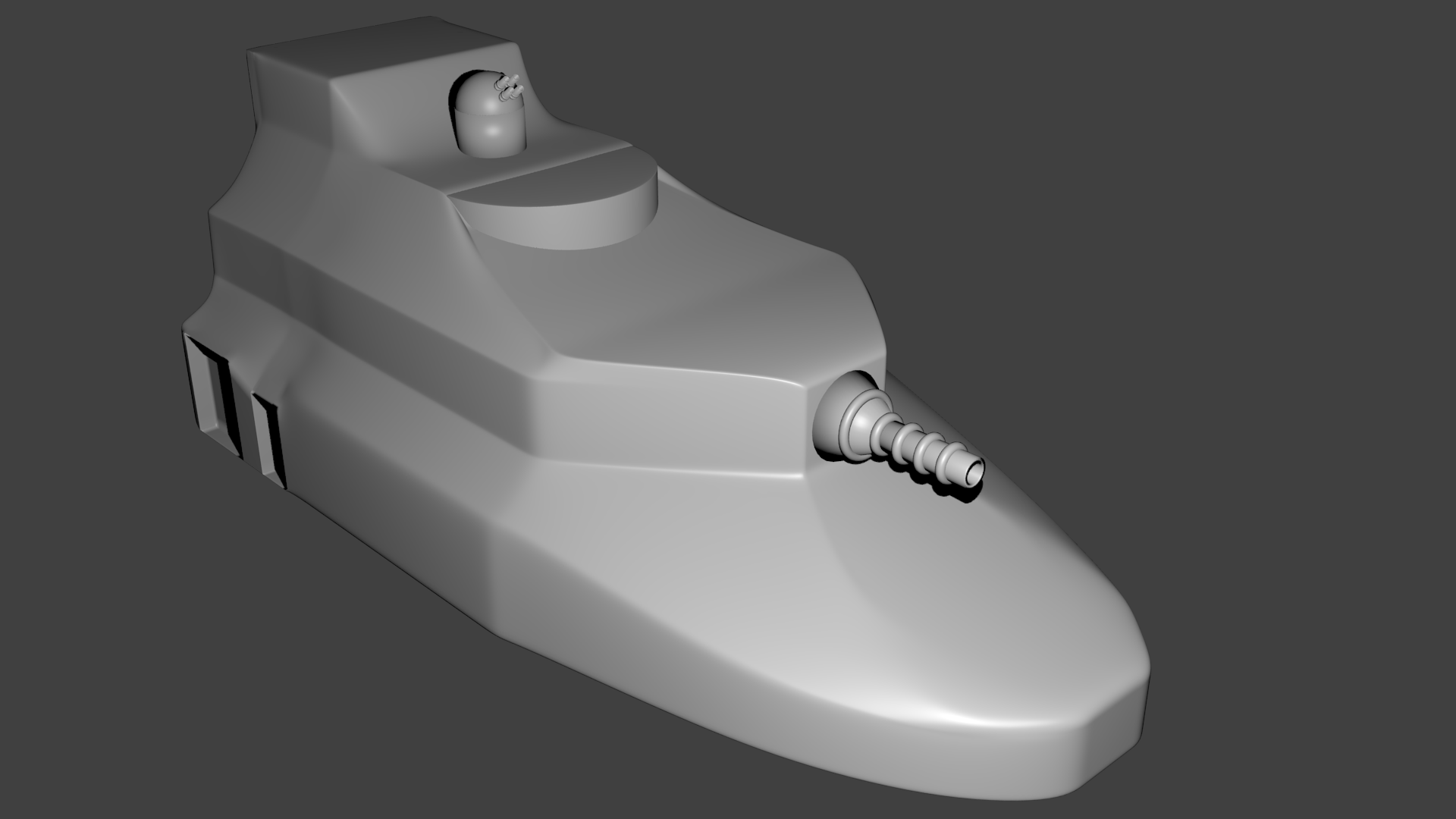
In both destroyer images from the game, this laser cannon is very obviously mounted outside the ship and visible on the exterior.  So I added an externally mounted cannon on the model. This gives a bit more room inside the ship’s bow and helps to match the profile on the counter better.

Engines

According to the rules, both the frigate and the destroyer are supposed to have three Class B engines.  The original frigate mini just had a single engine mounted directly aft of the ship.  Since I’m building this model from scratch, I decided to give it the three engines it is supposed to have.

I started by shortening up the cylinder on the model that was the actual engine on the frigate model.  I effectively just chopped off the nozzle portion and added a small taper to the end.  On the destroyer, this is now part of the interior hull space instead of the engine itself.

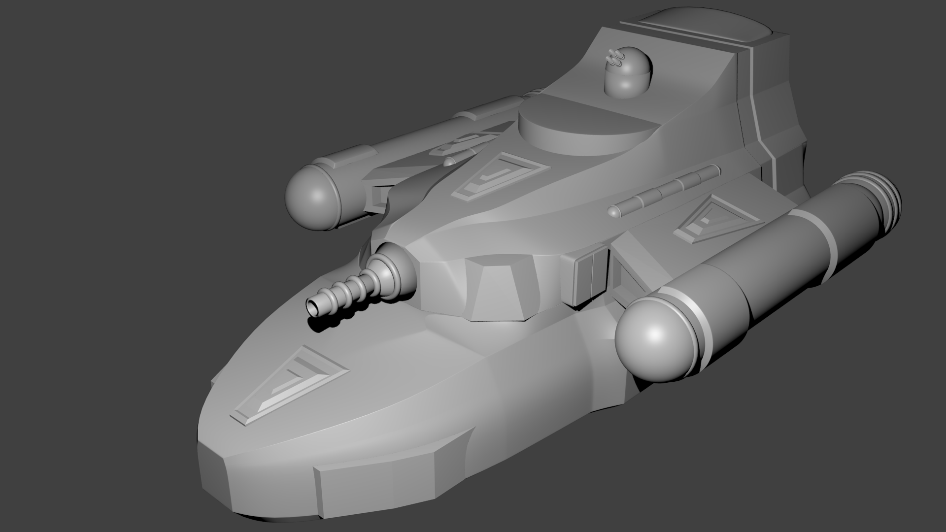
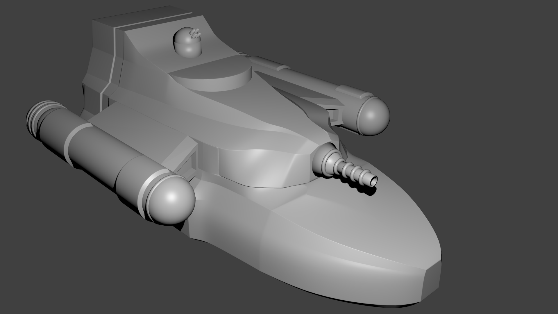
Next, I created an engine model.  It’s roughly the same size as the engine from the frigate but I gave it my own set of surface details.  I added an engine strut and then put three of them on the model distributed symmetrically around the tail section of the ship.

Finishing Touches

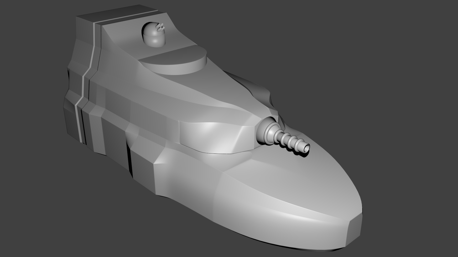
Finally, I went back and added a bit of surface detail to the ship.  Some of the bits were also used on the frigate and some I added in just for the destroyer.  That gave me the finished model. 

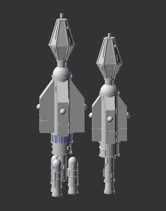
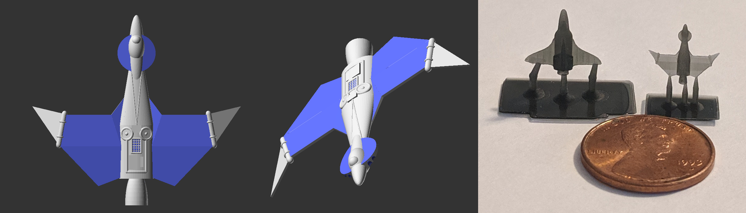
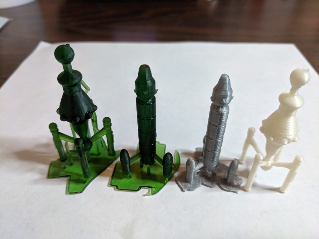
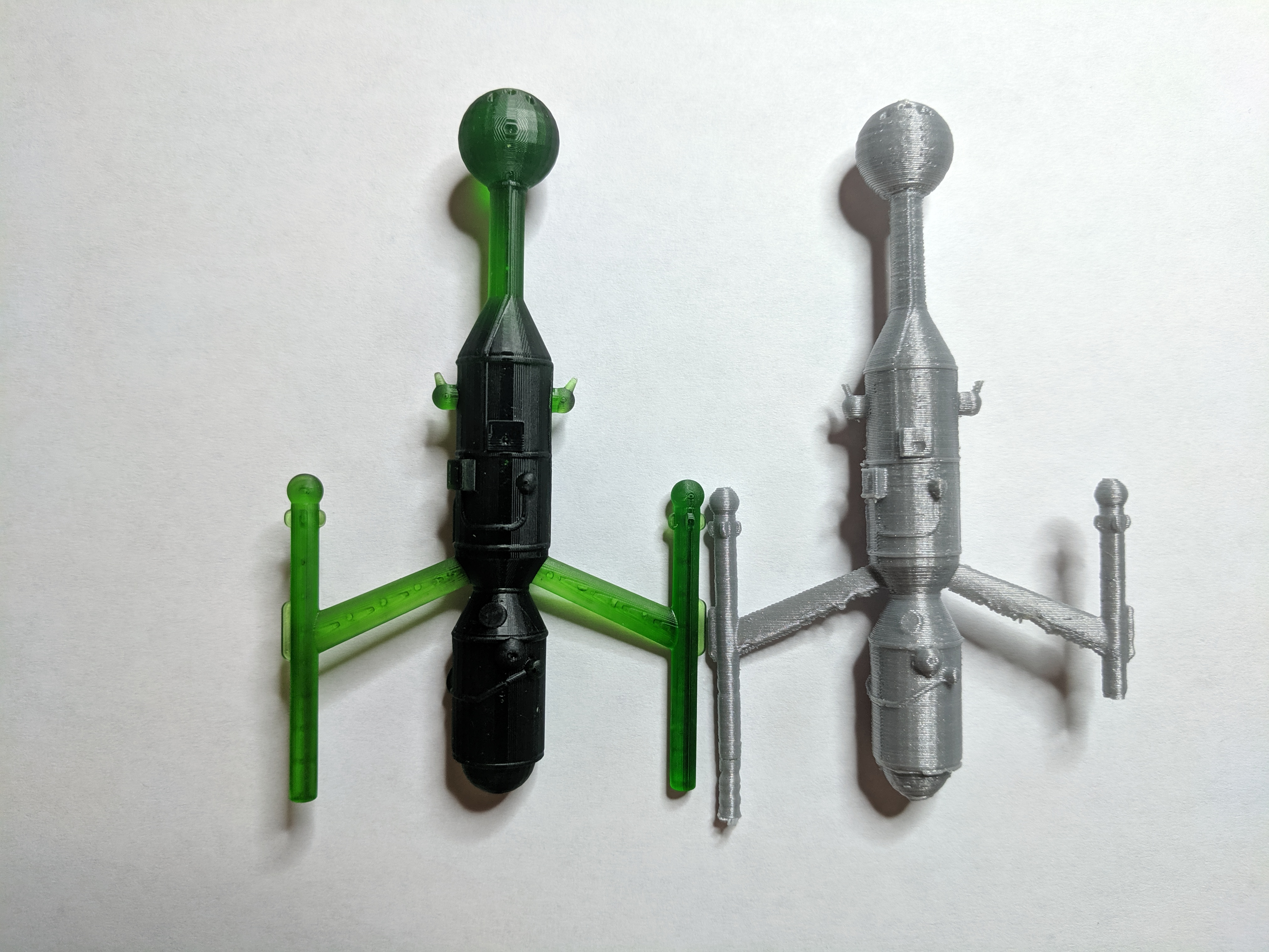
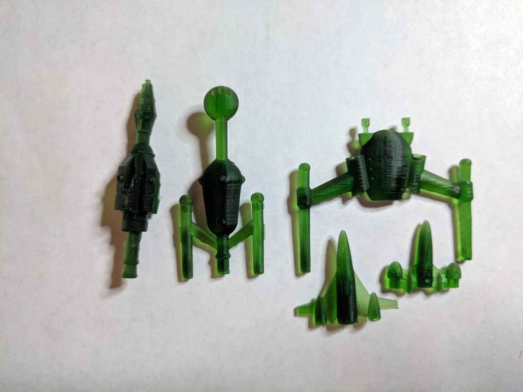
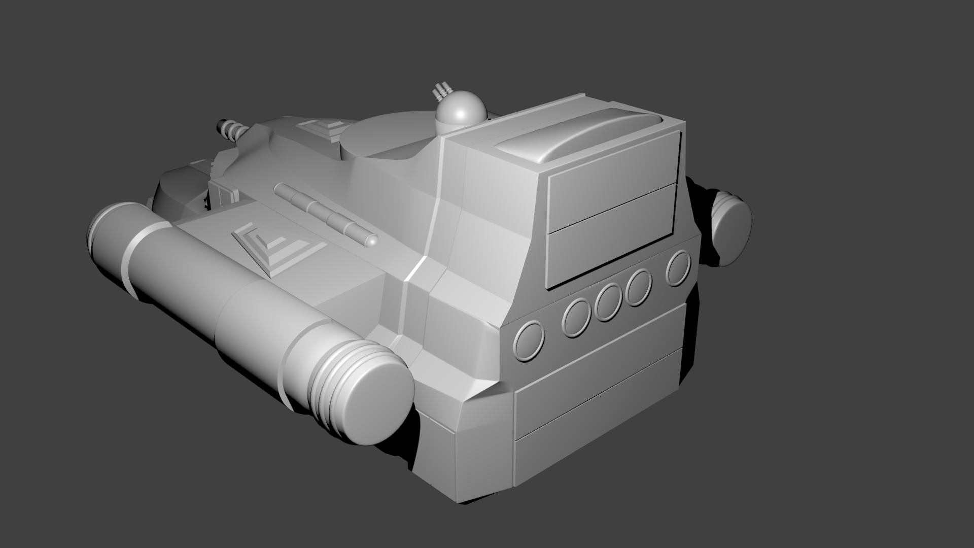
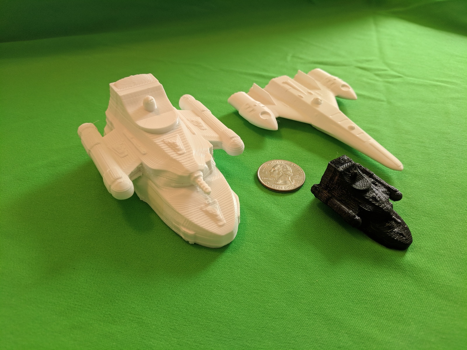
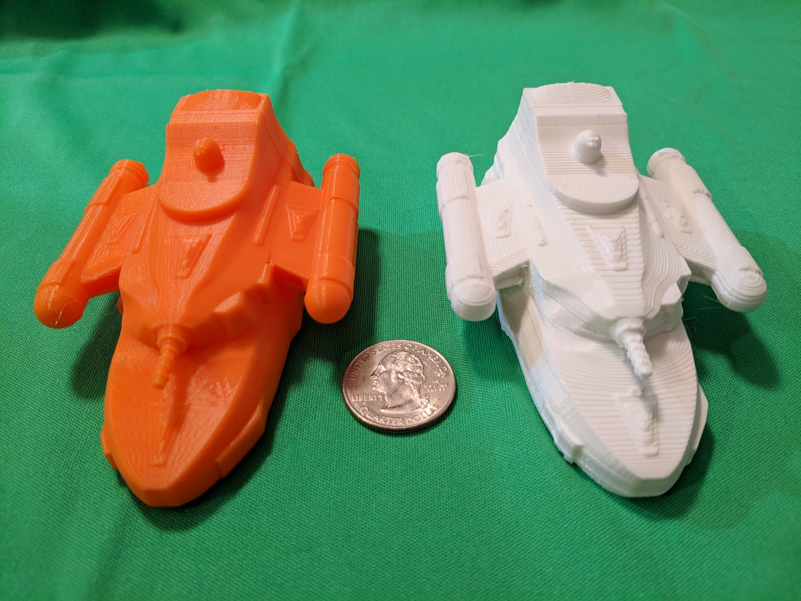
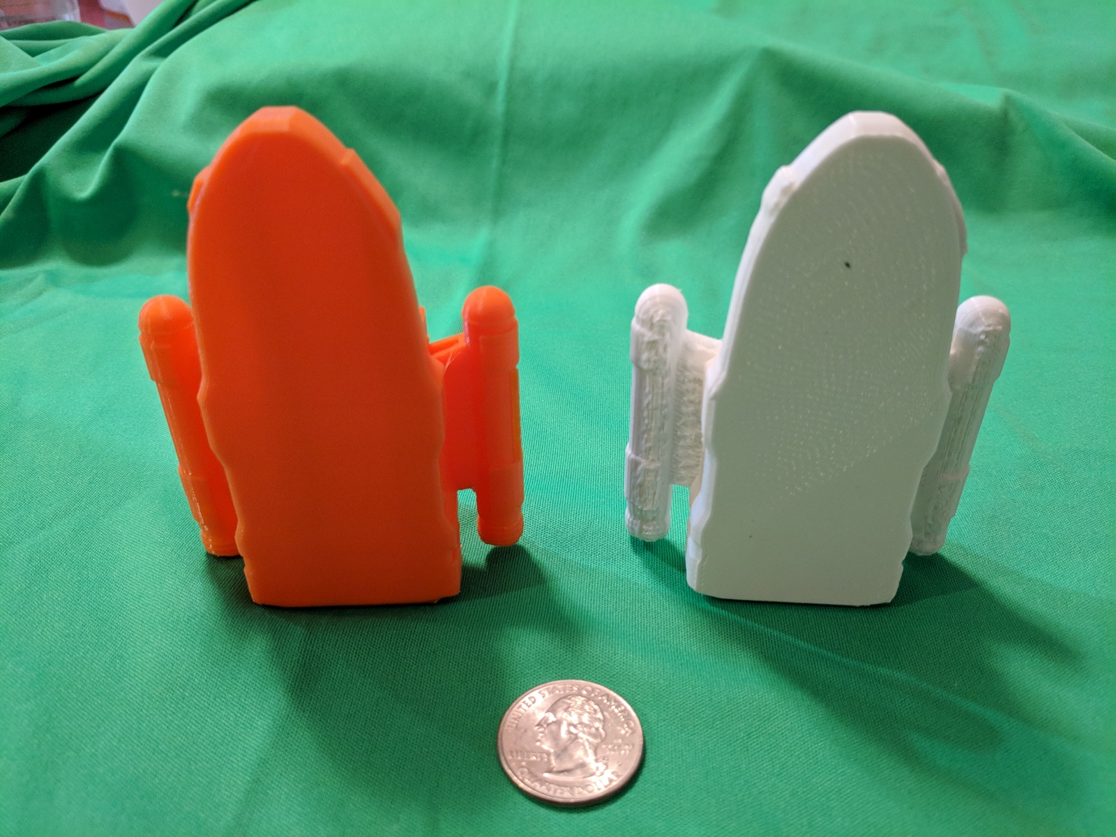
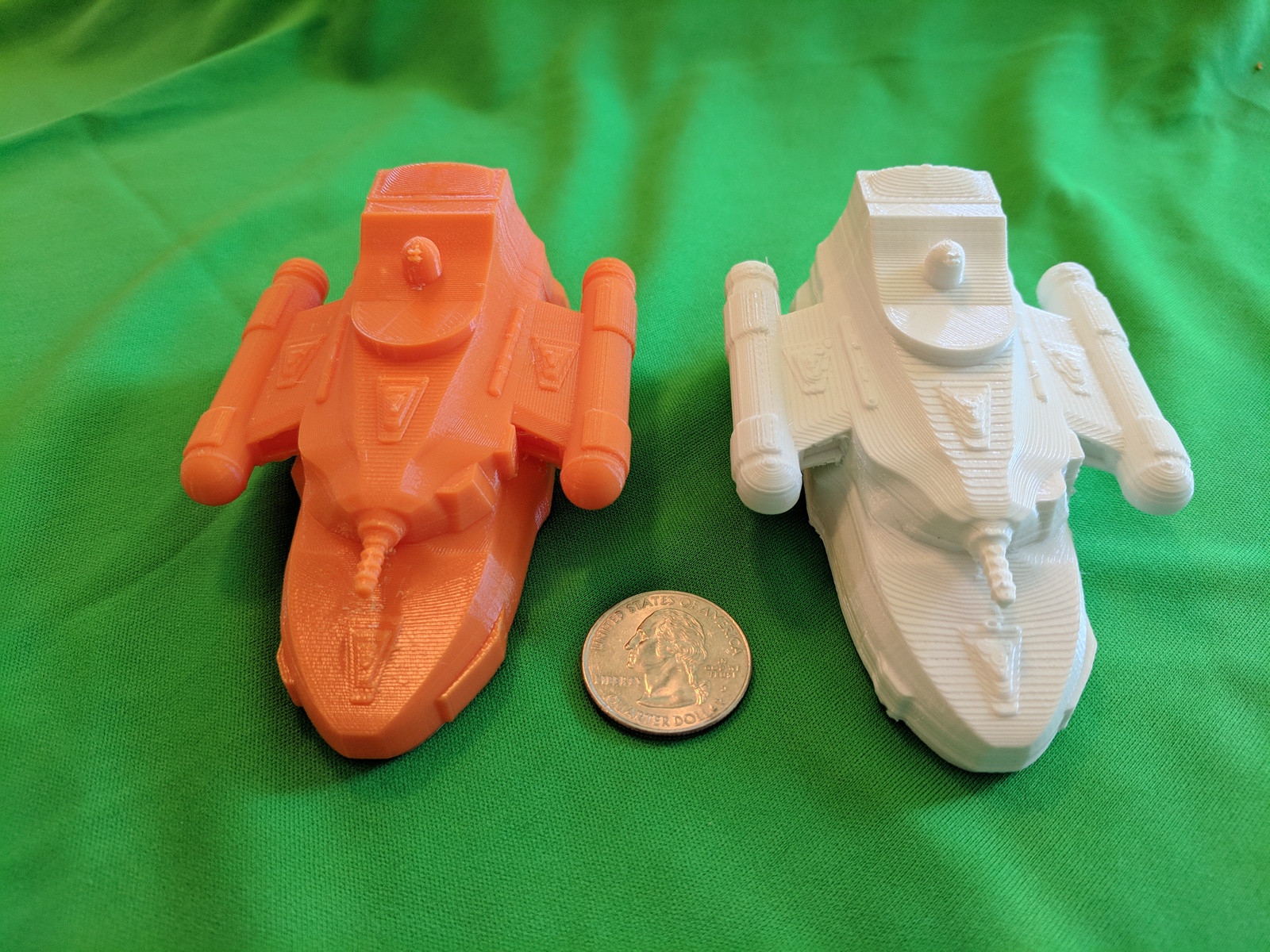
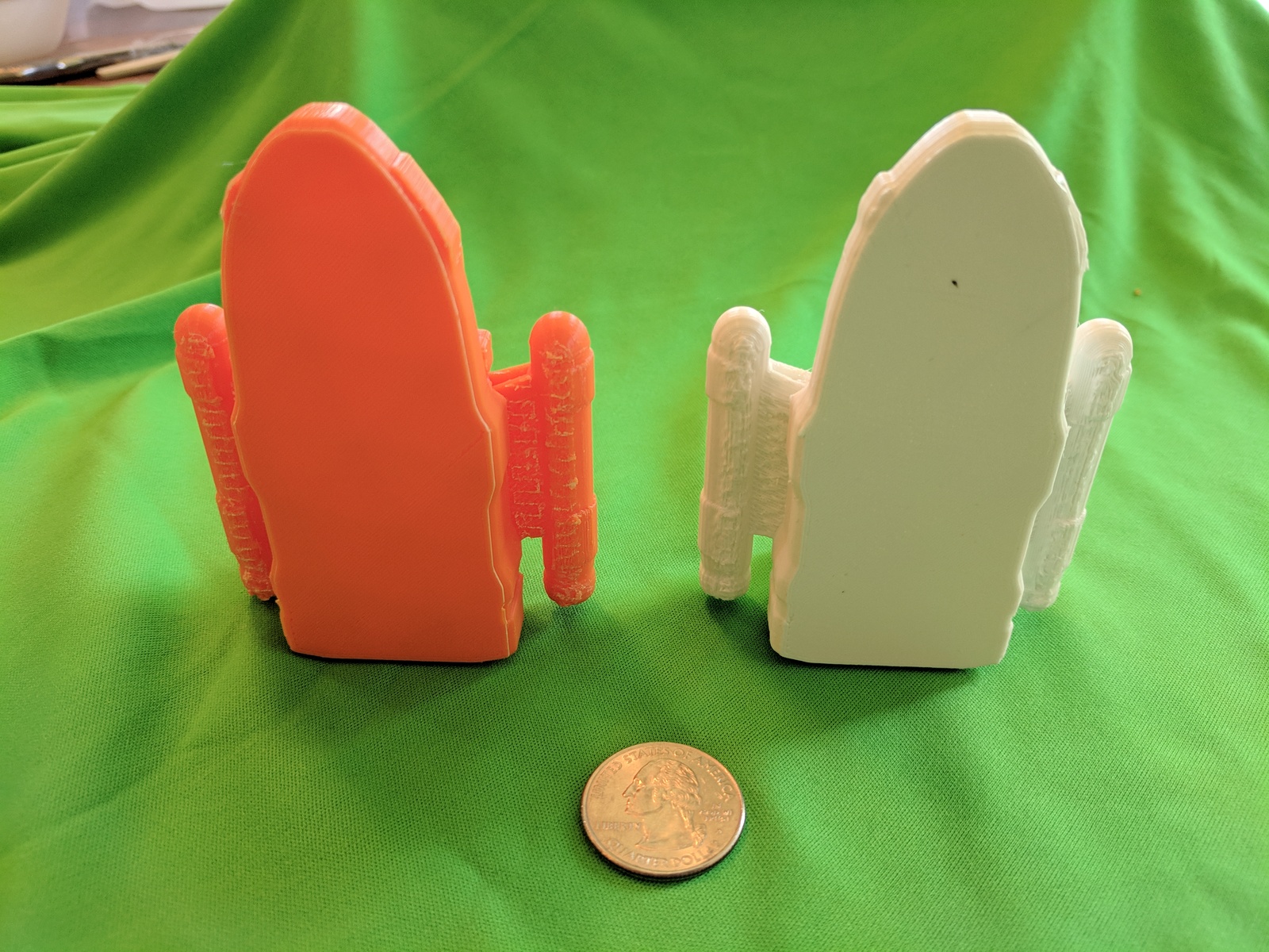
The image on the left shows the destroyer model alongside the frigate model for a size and feature comparison.  The image on the right is the other side of the destroyer model so you can see the externally mounted laser cannon a little bit better. You can click on either image for a larger version.

All told, the destroyer is about 58mm long while the frigate is about 52mm.  I realized after the fact that since the silhouettes on the counters are constrained in size, the actual physical size of the destroyer might be a bit bigger than I made it but it’s distinctive enough that I’m not going to worry about it.  Also, I feel better about the engine area being bigger, not smaller, than on the frigate.  When I do my complete custom builds, they’ll all be to the same scale.

Printing

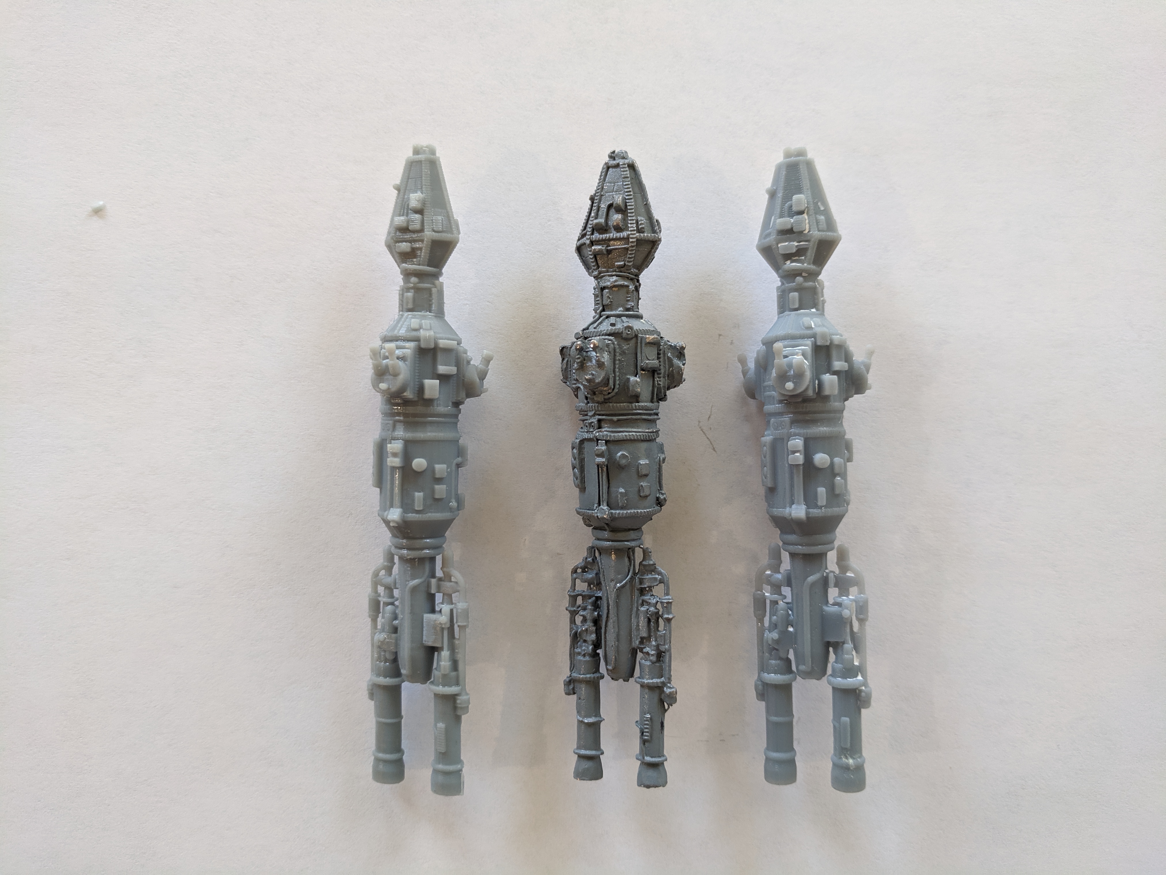
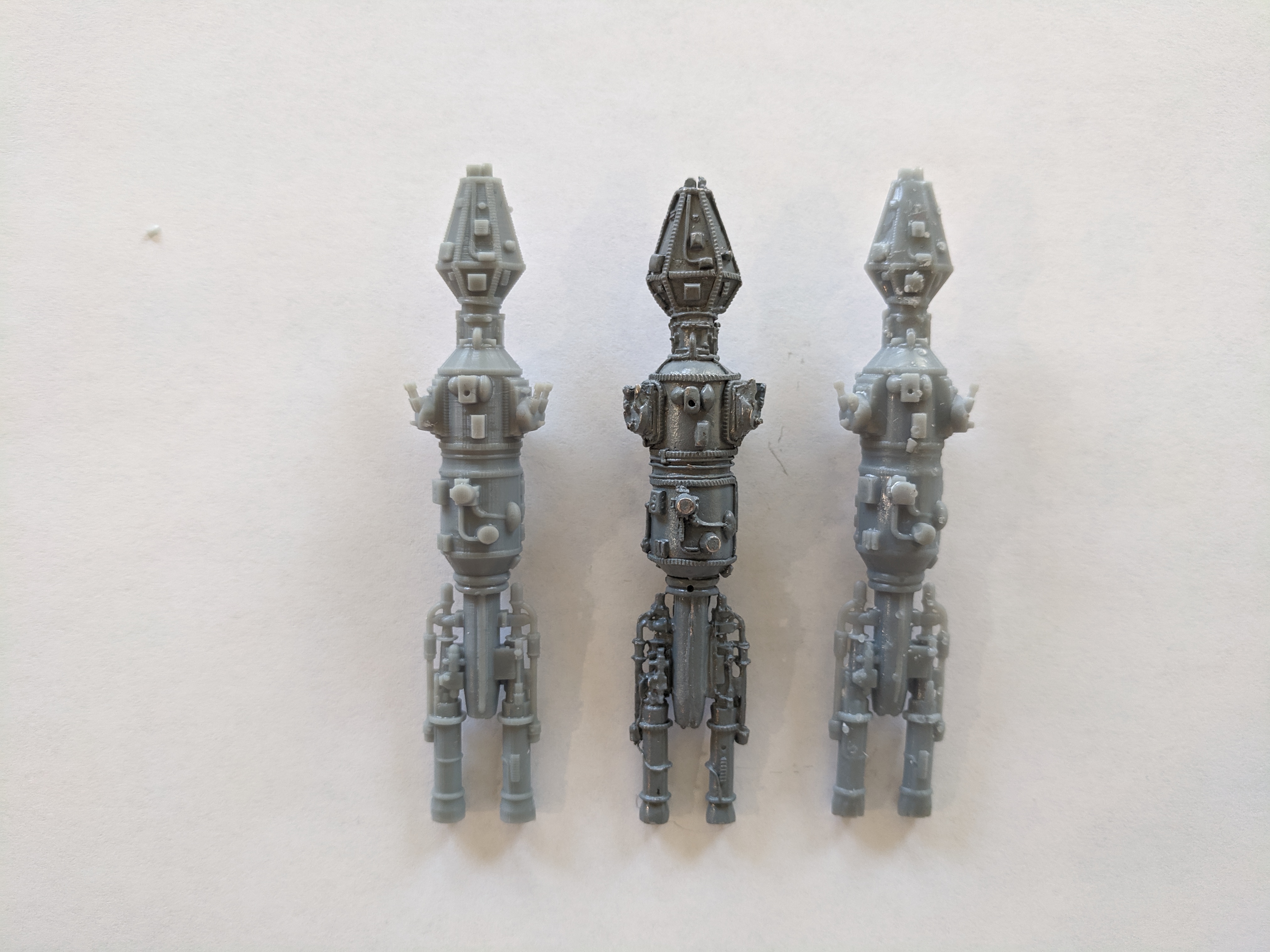
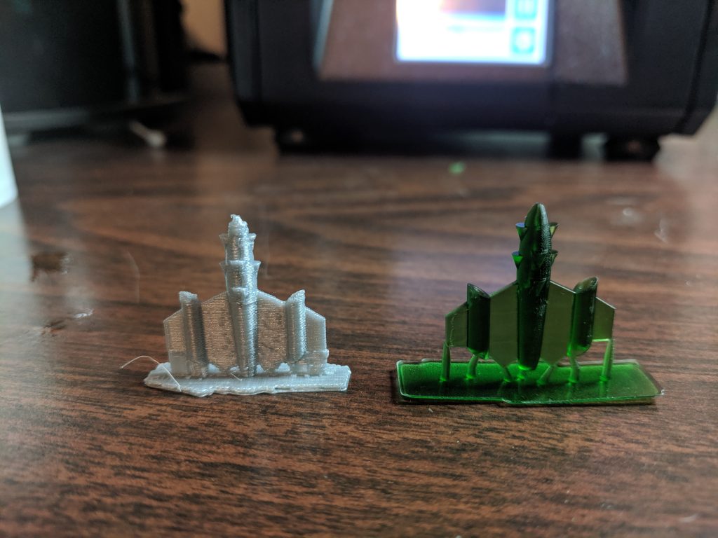
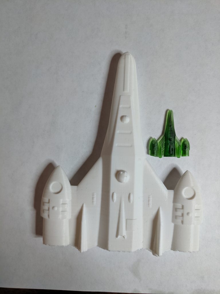
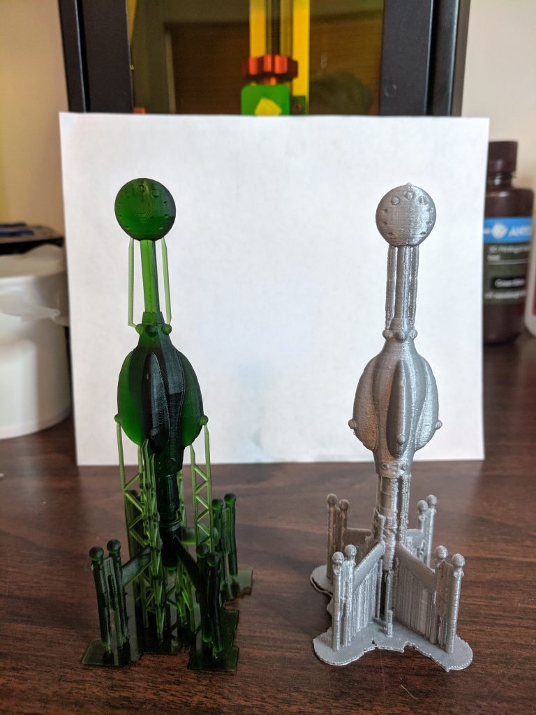
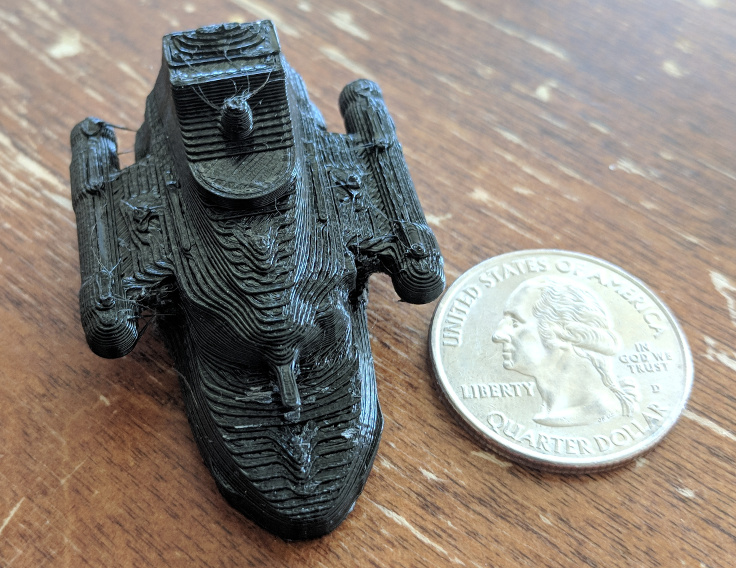
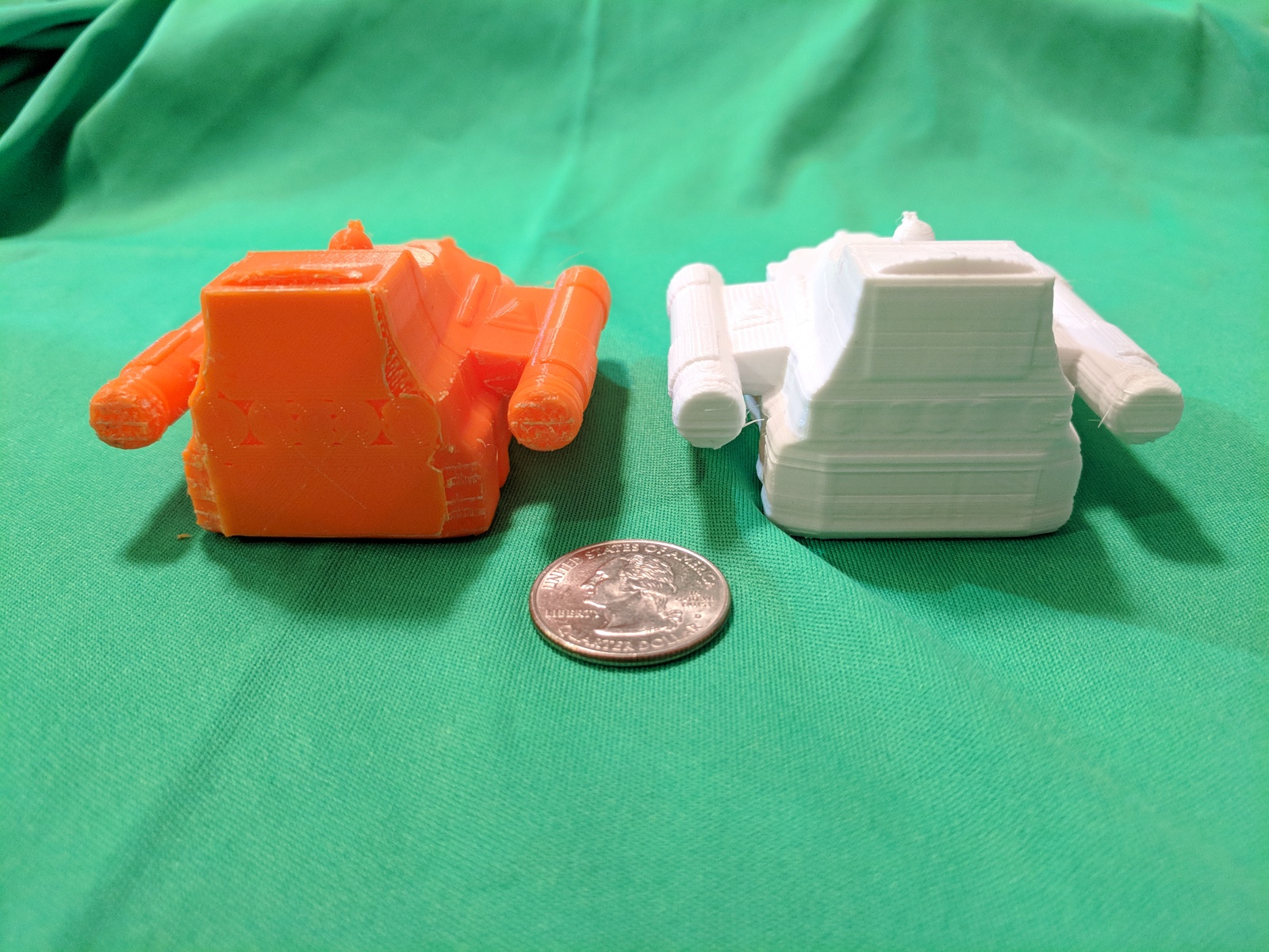
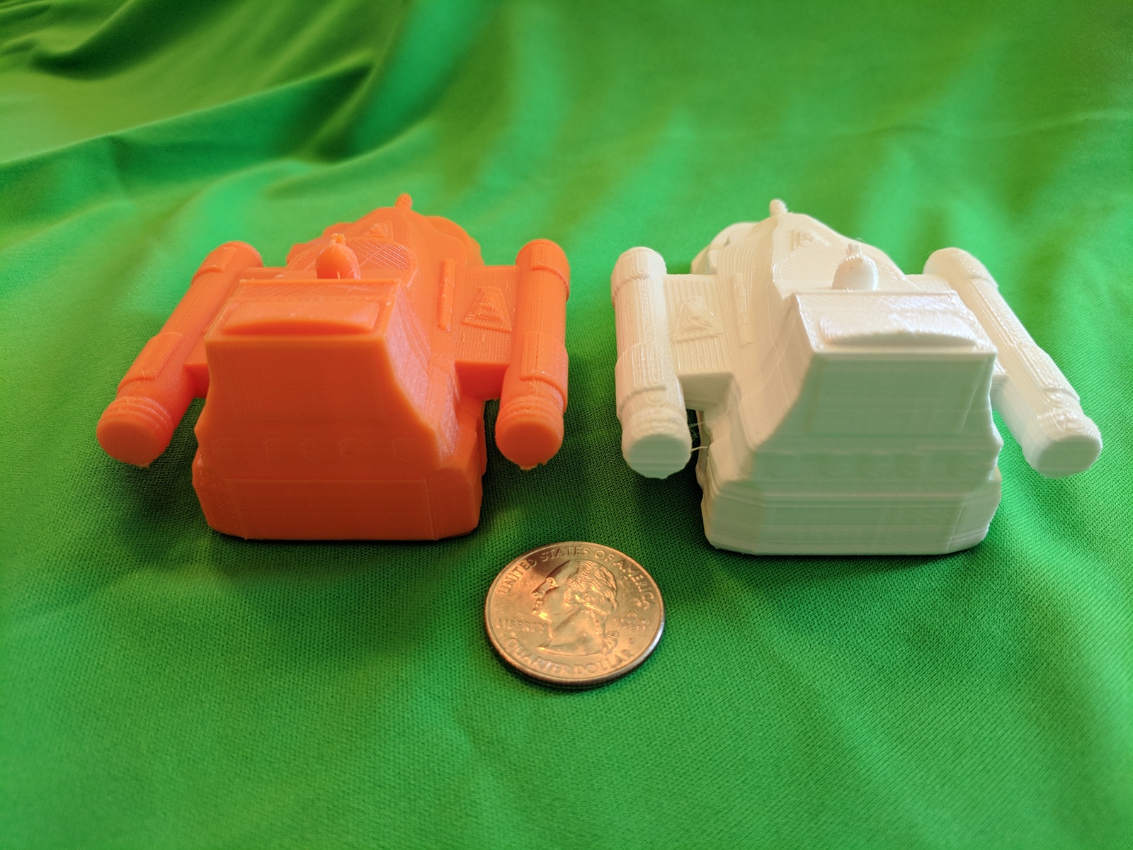
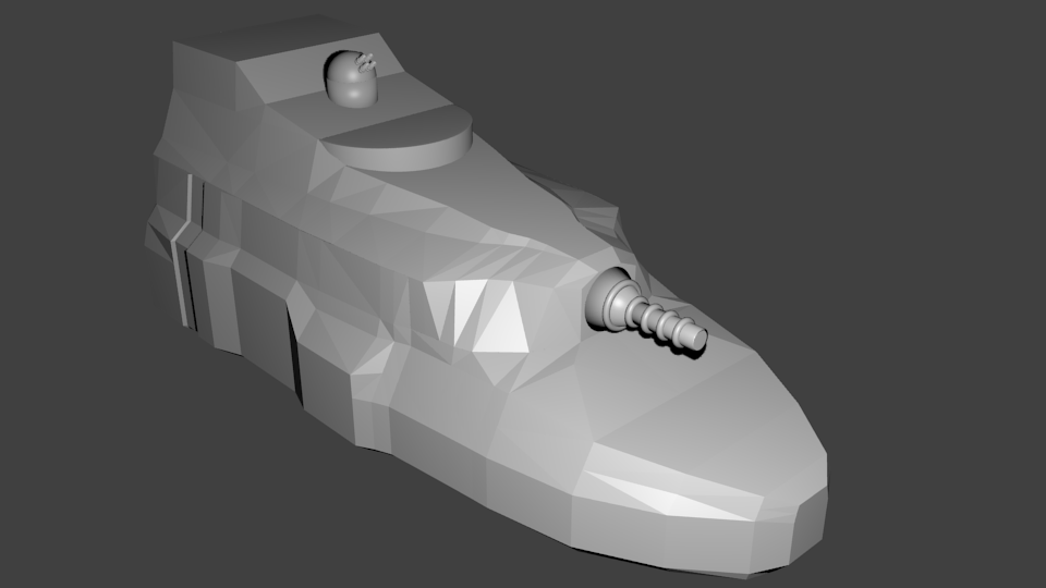
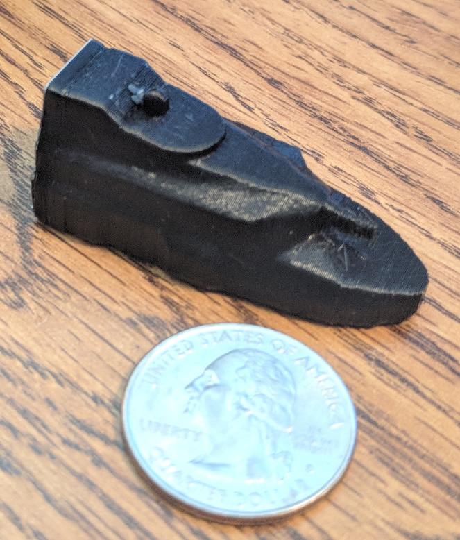
I got home from my trip yesterday and fired up my printer to try printing the model.  It worked out just fine with no issues.  The image below shows the printed destroyer alongside a printed frigate.

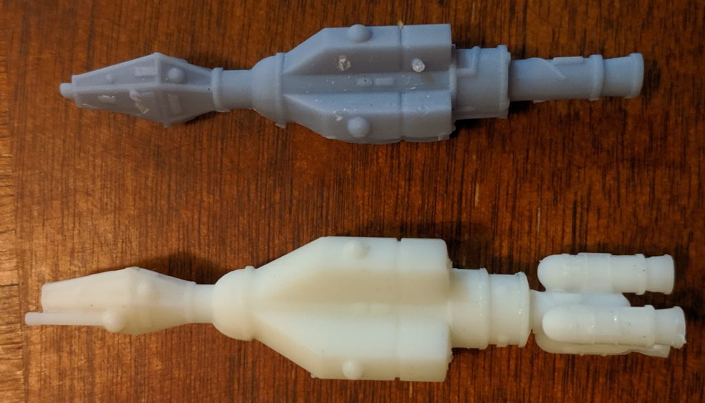
I decided to print the destroyer with the white resin which unfortunately doesn’t photograph well, so it’s kind of hard to see the details on it.  However, they are all there. 

Ship Stands

In discussions about the models on the Star Frontiers Facebook group, Jess Carver asked me about stands for the ships.  I hadn’t really thought about that yet but figured I’ve give it a go and see what I came up with.  I actually did this build a couple weeks ago before my trip.

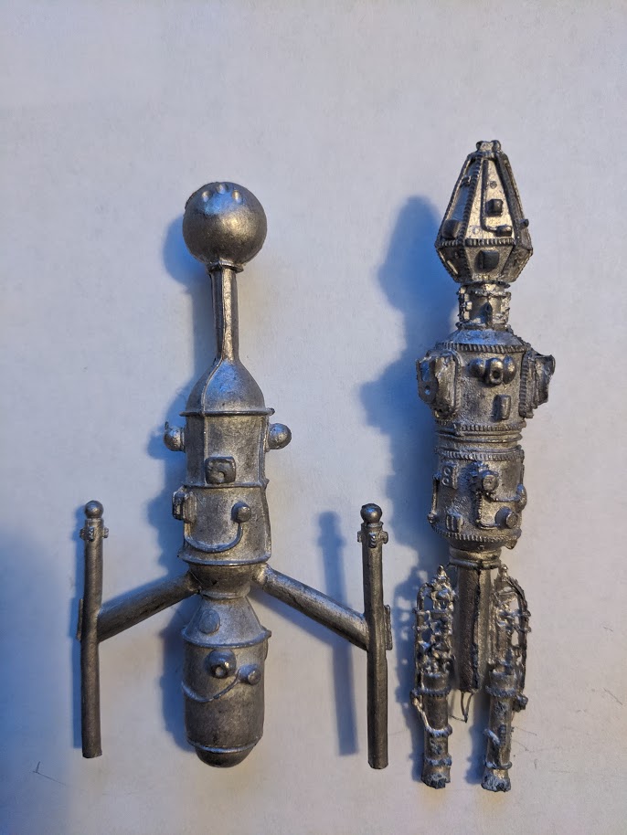
Looking at the stands that came with the original minis, they were just X shaped and designed to fit in a 1” square.  And they came with a small, 2” long, 1/32” diameter steel rod to mount the mini on. 

If you’re playing on a 1” hex grid, that original model stand is going to be a bit big and extend out of the hex the ship is in.  This could be a problem if you have a bunch of ships close together.  If you’re playing off a grid, that’s not so much of a problem but you then need a protractor to measure turns and such.  I wanted to make a stand that solved both of those problems if possible.

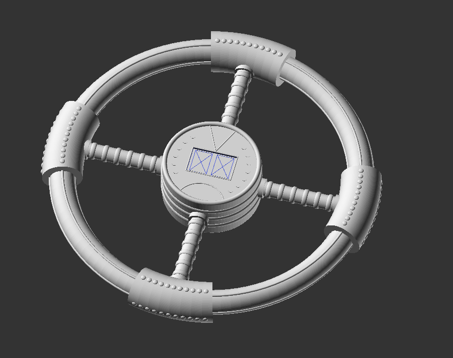
I started by making the stand circular instead of square and 1” in diameter.  I asked around a bit about what size hexes people were using as I have actually never played with minis, just the original counters from the game.  The answers I got back were 1” and 1.5” so I went with the 1” option.  It’s easy enough to scale the model up to 1.5 inches if someone wants that sized base and a 1” base fits in a 1.5” hex but not the other way around.

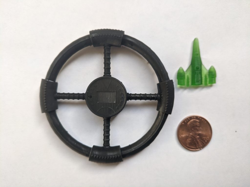
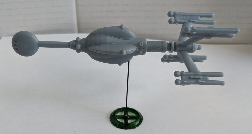
The outer edge of the stand is slanted back toward the center and I put tick marks all around it at 15-degree intervals.  It took a couple of tries to get the sizing right on these so that they showed up well on the print.  The first tries were a little to small.  You could see them, but you had to get close and that defeated the purpose.  I made the 60-degree tick marks larger to help find them better and added a unique tick mark at one position to represent the “front” of the ship or the direction of travel.  Here’s an image of the model.

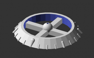
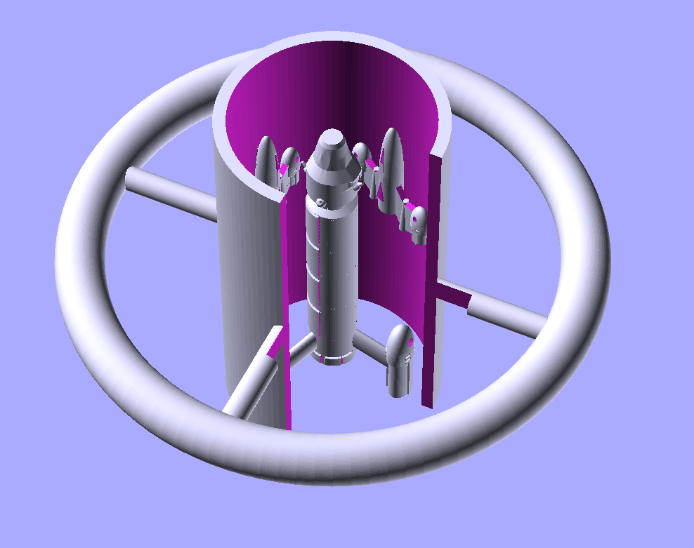
You’ll notice that it is just the base.  I made the decision to use a steel rod as the vertical piece instead of printing a vertical bar.  Printing it would require it to be a lot thicker and I didn’t want that.  Another thing that I discovered in printing the bases is that the hole in the middle that the rod is going to go into just doesn’t print well.  It keeps filling up with resin that would harden while printing.  I made the hole twice as large as the rod and it still didn’t work.  In the end I had to just drill out the hole for the rod.  Since I had to drill the models anyway, this wasn’t a big deal and probably better as the hole would be exactly the right size.  I did have to go buy a 1/32” drill bit since the smallest one I had at the time was 1/16”.

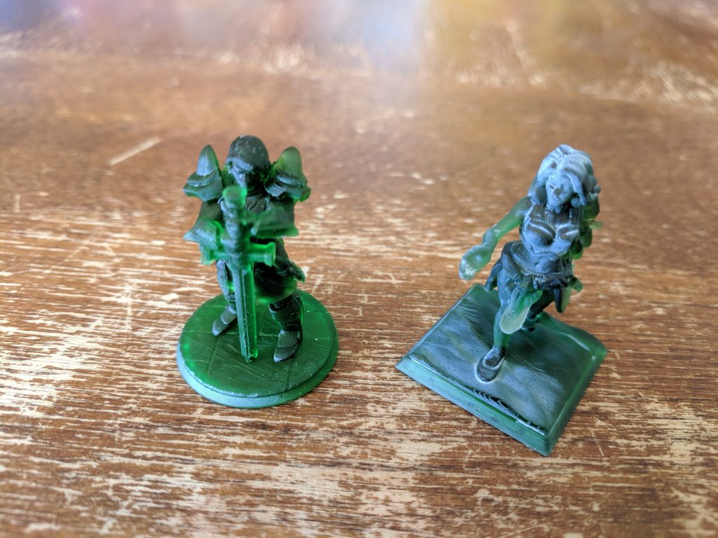
I was a little concerned about stability, at least when holding up the larger minis.  One inch is not that big when you compare it to a four- to six-inch miniature. So I gave it a stress test.  I grabbed one of my sathar heavy cruiser model, the largest one I’ve created at 5.5 inches, and mounted it on the stand.  I used one of the steel rods from my miniature boxed sets as I didn’t have any others.

It was surprisingly stable.  I gave it a tap and hit it harder than I intended.  The mini tilted by 10-15 degrees and then settled right back down on the base.  I deliberately tilted it in some different directions and it remained upright.  Obviously, you can tip it far enough that it falls over, but it seems to survive accidental bumping.  The plastic minis are much lighter than the metal ones so I’m sure that helps.  And if you want, you can always use two stands just like you had to do with the metal minis.

The only other issue was to find a source of steel rods.  I have the ones that came with my sathar and Federation ships boxed sets, but I am going to need more.  So I started looking around on-line.  I found some on Amazon that were 1.1mm in diameter (the ones from the boxed sets are 0.8mm) and 10cm long.  I wasn’t worried about length as I can cut them down to the 50mm size needed with my Dremel.  They were reasonably priced (20 for $8) but were shipping from Asia and would take a couple of weeks to arrive.  I kept looking.

I figured a hobby/craft store might have something I could use, especially if they sell model train supplies.  Sure enough, looking at Hobby Lobby’s on-line store they sold six 12” brass rods at 1/32” diameter for $4.  That was an even better price even including local sales tax. And I could just drive down and get them (about a 20-minute drive as the Hobby Lobby is a couple towns away up the freeway).  It took me a couple days to get over there but when I did, I found that not only did they have the brass rods I was expecting, they sold a four-pack of 12” steel rods for just $2.  An even better price.  So I bought a pack, went home, chopped up one with my Dremel, printed up a bunch of stands, and mounted up examples of some of my models.

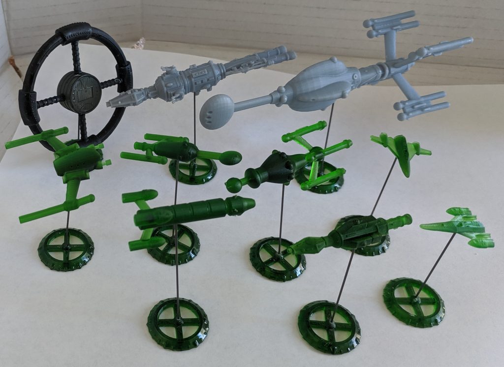
I’m starting to get the itch to print out enough of these and run a big battle on my kitchen table.

Final Thoughts

The build of the destroyer went really fast, at least partially because I was reusing the basic design of the frigate.  I completed it in just about four hours.  For comparison, the light cruiser model took something between 8-12 hours (I wasn’t really tracking it at the time) and I’ve spent 6 hours on the battleship and probably have another 6-10 to go.  Similarly, the stand build was really quick, maybe a half hour as it was a really simple construction and had minimal details.

The recreation models take a long time as I’m constantly measuring, placing, remeasuring, and tweaking the features of the model to try to match the original as closely as possible.  With a custom build, I don’t have that constraint and can just build the model as I wish so it can go faster.

This was a fun build and fills in a gap in the order of battle for the UPF.  Once I finish the battleship, the only remaining models will be the UPF heavy cruiser and assault carriers for both the UPF and sathar.  Since the miniature labeled as the sathar cutter on the blister packs matches the silhouette of the UPF minelayer on the counter, and I’ve already done that model, that ship can be used as the UPF minelayer if desired.  However, that ship definitely looks more like a sathar vessel so I’ll design a new minelayer for the UPF as well.

I’ve added the destroyer model and the stands to my price list on the Order Miniatures page.  Anyone that joins my Patreon as a supporter at the Crafter level will get all the models I’ve done this month (space station, light cruiser, destroyer, and a set of stands) mailed out to them in November.

Let me know your thoughts in the comment section below.

October 24, 2019 Tom Leave a comment

UPF Light Cruiser Model and Miniature

I didn’t think I would have this done by today but in a burst of fevered work, I finished up the light cruiser model so that’s what I’m writing about today. The image to the right shows the final model (click for the full-sized image). Let’s talk a bit about the ship.

First off, I’ve been calling this the light cruiser but on the Federation Ships boxed set of miniatures that the original came in, it is labeled as a Destroyer. However, it’s much too big to be a destroyer so I’ve always considered it a light cruiser, although it could arguably be a heavy cruiser also.

The frigate model is 2.25 inches long. Based on the size given for the frigate in the rules, this makes the model 1/2500th scale. The destroyer is only 30% longer and so at that scale should be about 2.9 inches long. This model is 3.75″ long. As a light cruiser it is a 1/3800th scale model which makes a little more sense to me. The battleship model is at 1/5900th scale so that would put it in between the scales of the frigate and the battleship and similar to the sathar light cruiser model which is at 1/3500th scale.

Here’s a picture of the two original miniatures side by side. They are roughly the same size (when I’m comparing them and quoting scales, I’m looking only at the fuselages and not counting the engines) and have basically the same volumes. So you’d expect the ships to be of similar sizes as well. So that’s why I’ve been calling this the light cruiser and not the destroyer despite what the box says.

With that out of the way, let’s look at creating the model.

The Fuselage

The first step was to build the basic fuselage that all the other bits would be attached to. This was fairly straight forward as it was mostly just some cylinders and cones hooked together. The calipers provided the lengths and diameters and that got us from the stern up to the neck just before the bow.

This is where I made my first deviation from the original miniature. On the mini, the bow is a hexagon from back to front so it extends out beyond the neck portion of the ship just a little on the sides. I decided to make if flush there and so used the software to smoothly transition from the circular neck to the hexagon, just like I had done on the frigate model.

At this point, I also added all the ridged trim to the edges of the model. I ended up making my trim a little more finely grooved than in the original miniatures. With that done, I had the basic fuselage and could start adding details.

The Engines

As you can see from the photo above, the engine structure on the UPF ship is much more complicated than the sathar one. That was part of the reason I started with the sathar ships several years ago when I first started making the reproduction models – it was simpler. However, I knew I was going to have to tackle this.

Then I got looking at the engines for the battleship model as well (they are not attached to the model like they are for the light cruiser). On closer inspection, I realized that they were exactly the same! Which meant that once I created a model of the engine, I could use it for the battleship as well.

So I busted out my calipers and started measuring. I quickly realized that that wasn’t going to work too well as there were little bits and pieces that I couldn’t reach with my calipers to make measurements. So I also took a series of images of the engines from each side that I could pull up in a graphics program and measure the number of pixels across a given feature was and convert that to millimeters to use in making the model. The result was the model to the right.

If you look closely, it’s a little bit cleaner than that one on the model. That’s because I’ll be 3D printing these and don’t have to pour molten lead into a mold. That allows me to leave of features that on the miniature look like they are there just to get the lead to flow into all the right parts. So it’s not an exact replica, but rather a close match.

The Guns

The next bit was to do the gun turrets. They are all the same and not quite equally spaced around the body. This was another instance of being able to make a single model and reuse it. It was also at this point that I discovered that there are two slightly different versions of the light cruiser miniatures.

Over the years I have acquired four different Federation Ships boxed sets, primarily in an attempt to get one that didn’t suffer from lead rot. It seems that these ships were particularly succeptable to that, primarily the battleship model. I finally ended up with two good sets, one of which had a coat of primer applied. In looking at the light cruiser models from these two sets, I noticed that the gun turrets were different between the two. On of the minis (the painted one) had more details on the turret than the other. I pulled out my other two cruiser minis to check and there was one of each in that pair as well. The difference is minor but I chose to model the more detailed version.

Again, like the engine, there were some features, mainly material supporting the gun turrets, that were there to help the lead flow into the mold that I left off in my model.

Details, Details, Details

With the easy and repeatable parts out of the way, it was time to start adding in the individual details all along the surface of the ship. I simply started at the stern of the ship and worked my way forward using calipers, rulers, and my good, old-fashioned Mark I eyeball (assisted by a magnifying glass) to determine the size and position of each of the features on the model.

The boxes, cylinders, and spheres were easy enough to add in as those are native shapes the modeling software I use produces. The really tricky part was all the piping along the body of the ship. Getting those shapes created and positions was a bit trick but by the time I got to the bow of the ship I was getting pretty good at the process and had built up some tools that simplified it that will help me in models going forward.

And then it was done. I wasn’t keeping exact track of the time but I think I spent something on the order of 10-20 hours producing the model. Now it was time to print.

Printing

If you remember from my review of the AnyCubic Photon printer, the print time is directly related to the height of the object printed. Since this model was small enough that it could lay flat on my print bed, I had two choices, flat or vertical. I was going to print this with the grey, opaque resin because I wanted to get more familiar with that resin and because it makes the details a little easier to see. The opaque resin takes longer to print and cure as you have to spend a little more time on each layer when printing (16 instead of 10 seconds). So printing flat meant a 3 and a quarter hour print while a vertical print meant a 12 hour print. In the interest of testing, I went with the shorter print (I really wanted to see a print that day and not wait all night).

Once the print was done and cured, I started looking it over to see how it compared to the original miniature. The “down” side looked fine, there were some variations but overall it looked fine. Then I turned it over. The “up” side did not look nearly as good and felt almost melted to me. I realized that this was from resin pooling on the upper surfaces and not draining off and then slowly curing during the printing process. I also noticed some warping due to not having enough supports in certain places. It looked like a flat print was not going to work. So I set one up to print overnight in the vertical orientation.

click for full resolution image

This first image shows the three minis side by side. The original metal miniature is in the middle (this is the primed one). On the left is the vertically printed mini and on the right is the horizontally printed one. This is the “down” side of the horizontally printed mini. Comparing the two printed minis, they look about the same on this side. Although I think the vertically printed one is just a little crisper.

Comparing the plastic and metal minis, I realized that despite always reducing the size of the features as I measured them off the unpainted mini, a lot of the features came out slightly larger. Also, the metal miniature still wins on the details in some places. I think I could fix that but I’m happy with the way it looks.

Turning the model over we get this view.

click for full resolution image

Here you can immediately see the issue with the printing on the horizontally printed model (on the right). The features are just not as crisp and clean. As I said before, to me it looked a bit melted. You can’t really see it in these images but the bow and ends of the engines are pinched and skinnier than the other model and the original. This is due to flexure in the printing process that could probably be fixed with more supports (I don’t think there were supports on the very tips because they were higher up and therefore didn’t technically need them). However, the issues with the remainder of the surface make this not really worth pursuing. This model will need to be printed vertically for best results.

Here’s another picture of the first side with the models in a slightly different orientation that includes a ruler for scale.

In this view, you can actually see a bit of the curvature I was talking about in the bow and engines of the model on the right.

Wondering if the opaque resin was part of the problem of the parts looking bigger or less distinct (due to the longer curing time while printing) I printed another vertically-oriented one win the translucent green resin that I did a lot of the other ships in. I don’t have a picture but I decided that there really wasn’t any difference between the two other than it was harder to see the details on the green one.

Final Thoughts

This model is good to go. I could tweak it in the future to make it look a little bit more like the original miniature but I’m happy with it the way it is so if I do tweak it, it will be some time in the future when I’ve got the rest of the line of ships complete.

I’ll be sending the model file out to my Patreon supporters later today. I’ve added this model to the price list on the Order Miniatures page for those that want to order minis for their collection. It’s priced just like the Sathar light cruiser at $2.75.

Some time in the next month (probably after we get issue 26 of the Frontier Explorer out the door), I’m going to start posting the model files up on DriveThruRPG for download as well. The models that are reproductions will be offered as pay-what-you-want while the ones that are original to me will have a small cost.

Next up is the UPF battleship. I already have the gun turrets (but not the bases, those are different) and the engines ready to go. There are a lot of repeated features on that model so it might go faster but it will definitely be November before it’s done. After that, I plan on filling in the gaps in the ship lines by designing a UPF destroyer, minelayer, and heavy cruiser, and then the assault carriers for the UPF and sathar. That will give all the ships necessary for full fleet engagements. After that I’m going to go back and tackle the pirate frigate, freighter, and privateer minis from the original sets to complete all the reproductions. There might be some new ships thrown in along the way as well.

Feel free to share your thoughts and comments below.

October 15, 2019 Tom 4 Comments

Armed Station Model and Miniature

I teased this model in the last State of the Frontier post where I showed a picture of the printed miniature. In this post, I’ll talk about the creation of the Armed Station model and miniature that I created as part of my current interest in doing more 3D modelling.

Scale and Sizes

The basic outline of this model is based on the space station counter that came with the Knight Hawks boxed set, pictured to the right. For scale, I assumed this to be a HS 6 station making the diameter of the station 1200 meters, just short of a mile. In the end, the model was a bit bigger than that as I set the diameter of the center of the ring to be 1200 meters but that’s a minor quibble that can be fixed if really wanted by scaling the final model.

When I do my modeling, I typically work at 1/1000 scale in the model files so 1 meter on the actual vessel is represented as 1 mm in the model. However, for the space station, that was just a little bit too bit so instead I worked at 1/10,000th scale or 1mm = 10 meters. In the end, at that scale, the model came out at 137.4mm across, or 5.4″.

With the outer ring having a diameter of 1200 meters, that gives us some dimensions of other parts of the structure using the counter image as a silhouette.

The Main Ring

First is the cross sectional size of the ring itself. I chose to model the ring, at least for this version of the model with a circular cross section. I may do a future one with a square or rectangular cross section. Regardless, at this scale, that give the ring a height of 100 meters in the radial direction. So for the model, it has a diameter of 100 meters

That means, assuming you have 5m per deck, you could put 20 separate decks in the ring of the station, with the widest deck at the center being about 100m wide and the decks getting narrower as you move up or down from the center. The upper (and lower) two or three decks would be fairly narrow and probably used for machinery and other non-public areas.

The Spokes

On this station, the spokes connecting the hub to the ring are 60 meters across. Again, I chose to use a circular cross section so they are 60 meters in diameter.

In addition to the spokes of the station, the counter shows a thicker “sheath” around the ring where the spokes meet it. This sheath is 164 meters in diameter compared to the 100 meters of the ring. That means that there can be an additional 12 decks in this section of the station.

The Hub

Let’s start with what we can see from the picture on the counter. Measuring this out, the hub is 400 meters in diameter. That is the same size as the outer diameter on a hull size 2 station! But that’s fine. This is a big station and is supposed to be able to dock a lot of ships of all sizes.

That brings us to the first constraint. According the Star Frontiers rules, a hull size 6 station can dock any sized ship, including the HS 20 ships. Those ships are 100m in diameter. So the bay opening into the hub has to be at least that big. As drawn, in the counter, it’s only 85 meters wide so we’ll have to make it a little wider but that’s not that big of an issue. I ended up modeling it 110 meters wide. A HS 20 ship will fit, but it will be tight.

The harder part is the length of the hub. Those same HS 20 ships are 600 meters long. Or equal in length to the radius of the entire station. For our hub to be able to house those ships inside as the game implies, means that the hub has to be really long, at least 650 meters (to handle variations in width/length both the door and length should probably be larger but that’s what we’re going with here.) This results in a station that looks like this.

I tossed in some HS 18 Sathar heavy cruisers for scale. There’s also a HS 6 freigher (the CDCSS Nightwind) there to the right of the hub.

The same is true for the smaller stations. This image is one I made a long time ago of a HS 1 station which is just 200m in diameter and supposed to be able to house up the HS 6 ship. This shows a cut away of the hub with the CDCSS Nightwind inside along with a couple of assault scouts. I didn’t put bay doors on this one, as it was just for scale comparisons.

Personally, I don’t like the hub that big and in my game, the bigger ships don’t dock inside the hub. Rather they just enter a nearby parking orbit and material and people are moved across by shuttles, which can dock in the hub. So for the final version of this model, I made the hub just 200m tall instead of 650m. That’s still big enough to dock up to a HS 8 ship inside. In a future version, I might make it a little bigger, at 250-260m allowing a HS 10 ship to dock inside. But anything else starts to look a bit to big.

Finishing up the Model

Once I’d decided on the size of the hub, the basic shape of the station was done, but it was pretty boring looking. So I decided to add a bit of surface detail to the model to make it a little more visually appealing.

First I created bay doors that I could position either open or closed. In the end I decided to print the model with them closed but I created models with them both open and closed.

Then I added some surface detail all around the ring, spokes, and hub to give it a little character. In the end, the final model looked like this.

The asymmetry in the number of pips to the left and right of the doors was accidental. But I decided to leave them. The V-shape and half moon shape above and below the bay doors where intentional as navigational markers. The side with the ‘V’ that touches the bay entry is the “up” direction to orient ships aligning with the bay for entry. the opposite side of the hub is identical.

Printing the Model

As I said earlier, the completed model, at 1/10,000th scale is 137.4 mm. The problem is my high resolution printer has a maximum width of 120 mm. So this is just a bit too big. It’s not too tall, the limit there is 155 mm. And it’s not too thick as it can be 68 mm wide and this model is only 22mm wide (that would have been a bigger issue if I’d gone with the fat hub). I could easily print it on my big printer; in fact, I could print it at 1/5000th scale if I wanted to) but that wasn’t the plan. I wanted to print it on the SLA printer. If I rotate it just right, the software says it is possible to print the station at 1/10,000 scale in the build volume I have. And I might try that one day

However, from the beginning I had planned to print it at 1/20,000th scale which makes the largest dimension just 68.7 mm or 2.7″. So that’s what I did. You can see the result in this image.

The station was printed with black resin, the assault scout is 1″ tall and printed in the green resin that came with the printer.

The only detail that doesn’t show up is the “X” on the bay door. They are there, but very, very faint. I might go back and thicken them up in the future so they show up better on the print.

Final Thoughts

Given the size of the station, if it is spinning such that the deck at the center of the ring has a gravity of 1.0g, then for every 60m you move toward or away from the center of the station, you gravity will change by 0.1g. This means that the upper deck, 45m above that position will have a gravity of 0.925g while the outer deck will have a gravity of 1.075g. In the part of the station where the spokes connect, assuming there are decks all the way out to the edge, you get a range from .87g to 1.13g. And the hub with a radius of 200m, has a gravity of 0.33g, roughly the equivalent of the surface of Mars.

That raises an interesting point. The docking area in the hub is supposed to be fairly low gravity. I wouldn’t consider 0.33g to be that low so the hub is probably a bit too large in diameter. But it looks cool so it’s fine for the model.

The model has already gone out to my Patreon supporters at the Surveyor ($2/month) or higher. If you join at that level you’ll get access to it as well. Anyone that joins at the Crafter level ($30/month) in the month of October will get a printed version of the model as well as 8 UPF and 8 Sathar fighters. I’m also planning on posting the UPF Light Cruiser this month (the model is almost done) so a printed mini of that model will go out to backers at that level as well. Those will all be printed and shipped out in early November.

If you don’t want to back the Patreon, but still would like to get a print of any of the miniature models I’ve created, you can jump over to the “Order Miniatures” page to see the costs for the minis and place an order.

Let me know your thoughts and comments on the Armed Station model and miniature in the comment section below.

October 8, 2019 Tom Leave a comment

Fighter Miniatures

I’ve been bitten by the 3D modeling bug again. It started with me creating this page here on the site. I figured that since I had my high resolution 3D printer and a bunch of 3D models I had already made, I could offer the opportunity to print them for those that wanted them.

So after creating the page, I posted a link to in in the Star Frontiers Facebook group and got quite a number of comments. One from Andy Campbell, which suggested that I make “scenario packs” – basically providing all the minis needed for a given module or scenario from the rules, was very close to something I had noodling around in the back of my head already. The problem was, I only really had the sathar ships and a few of the smaller UPF and pirate vessels like the the Assault Scouts, UPF Frigate, and Corvette.

Plus there are a number of ship designs for which no official miniature was ever released such as the fighters, the UPF Destroyer and Heavy Cruiser, and assault carriers for both sides. There’s no official Sathar Destroyer either but I’ve already made that one. I’d need to make models for those missing ship types if I was going to to pull this off.

Now, I already had plans to create the Sathar Assault Carrier. It was one of my original project when I started this blog. So I think I’ll be getting back to that one shortly. However, to get started I wanted to start on something small, and something there were some art references for. I also wanted to test out how small of a miniature I could reasonably do with my printer.

I had a Sathar Fighter model that I had created several years ago but it was based on a fan created fighter drawing and had just a bit too much resemblance the the rebel logo from Star Wars. I had also played around a while back with the idea of making 3D counters, basically versions of the ship counters that came with the Knight Hawks game but with raised reliefs of the ships on them instead of just being flat. I had made one of the UPF Fighter so I had some experience modelling that one. So that’s where I decided to start.

UPF Fighter

I made this model based on the image on the counter that came with the game. It has a short stubby rudder and is somewhat atmospheric capable. I didn’t put any detailing on the engine package at the back as shown on the counter but I might go back and do that at some point. However, it’s really small so the detail would be mostly lost anyway in a physical miniature.

I do all my ship modelling at 1/1000 scale so that 1mm on the model equals a meter on the actual ship. Since according to the rules, the fighter is a hull size 1 ship, that means it is only 10m long. The ship ended up being 11m in size as I gave the 10m size to the fuselage and tacked on an extra meter for the engine nozzle at the back.

This model was printed at full size (1/1000th scale). That means that the printed miniature is only 11m long and about the same wide. For the capital ships, I typically print them at 1/3000th scale as that is roughly the scale of the officially release miniatures. However, printing these fighters at that scale would make them absolutely minuscule. It also wouldn’t have printed properly as the wings would have been too thin. As is, they are just a bit larger than the thinnest piece I can print with this printer. This is a little, tiny model and you have to be careful because if you’re not careful, it might just blow away. This is now my UPF Figher MK I miniature.

That one worked. And it only took me about 3 hours to make the model. What’s next?

Sathar Fighter

As I said earlier, I have a model of a sathar fighter that I created based on a fan image (the model and image that inspired it is to the right). This one was designed to be printable on a FDM style printer with 0.1mm layer resolution and it works. But it is a very simple model. And I had always called this my Sathar Fighter MK II model as I knew this shouldn’t be the original. What I wanted was one that matched the silhouette on the counter that came with the game.

For this fighter model, in addition to the game counter (at left), there is this great illustration from page 54 of the Knight Hawks Campaign Book showing this same fighter being pursued by another fighter. So we have some more detail to go on for this one.

This model was going to take some more work. With the bent wings and contoured surface, on the cockpit disk and the wings themselves the modelling was going to be a little more complicated.

Again I went with a 10m length, this time including the engine nozzle in that 10m. Since I’m still modelling in OpenSCAD, I started creating little modules that will allow me to reuse some of the elements I created along the way in other ships if I need them.

This model took me a bit longer. I was getting back into the groove of modeling and so getting faster, but this one was a bit more complicated. In the end, this model took me about four hours to finish but I really like the way it turned out. Here is a couple of view of the model, plus the printed version side-by-side with the UPF fighter.

You can’t see it in the picture, but that detail that I added on the back of the fuselage is just sort-of visible on the printed model. Which means I should go back and add some detail to the UPF fighter as well. As it currently stands, this model is only printable on my SLA printer as the wings are almost exactly one resolution element (0.05mm) thick. In fact, I wasn’t sure it was going to print and was relieved to see that it did. I will probably go back at some point and make the wings a little thicker. If or no other reason, to make them a little stronger.

Compared to other ships

Here’s another comparison image showing the two fighters next to a small assault scout mini (my Swift-class assault scout model printed at 1/2000 scale), and a replica of the officially released UPF frigate mini which is also happens to be at nearly 1/2000th scale. So the two larger ships are roughly to scale with each other but the fighters should be half again as small to be on the same scale.

Future Models

At the very least, I want to make a second UPF Fighter (Mk II) mini that matches the ship depicted chasing the sathar fighter in the image above. There are also some other fighter-like ships depicted throughout the illustrations in the rules that I might take a crack at.

Also, if you are at all familiar with the rules, you know that these fighters as depicted could not possibly match the stats given for them in the game. These fighters are supposed to be packing three assault rockets, each of which is roughly the same size as the fighter’s entire fuselage. One of these days I’ll make a model that depicts that.

But first, I want to start seriously looking at finishing off the line of ships so I have a model of each ship type. I’m also going to need some space stations. As I’m writing this, I’ve already made my first space station model. I’ll post about that here in the future but if you are following me on Twitter or are a member of the Facebook group, you’ve already seen some pictures of that model.

Getting the models and minis

My Patreon supporters at the Surveyor ($2/month) or higher level will be getting copies of the model files for each of these models (and all future models as well). If you’d like to get them as they are produced, consider signing up to support this work. In the very near future, I’ll also be putting all my model files on-line, probably on DriveThruRPG for everyone to access.

If you’d like to get 3D printed miniatures of any of the models I’ve created, you can check out my Order Miniatures page which gives the details on how to order them and lists the prices.

September 24, 2019 Tom Leave a comment

AnyCubic Photon – A 3D printer review

As you know, I like to build models and 3D print them. I’ve had Rostock Max v3 printer for a couple of years now that I’ve been very happy with. With it’s ~11″ diameter bed and ~16″ maximum height, it has allowed me to do some really large prints like my 12″ Assault Scout and my dice towers. I’ve also used it to print parts to repair things around my house or other useful gadgets.

Types of Printing

As a fused deposition modeling (FDM) printer with a 0.5mm nozzle, one thing the Rostock doesn’t do is super fine detail on small scales. It’s good enough for the spaceship models I’ve been making, especially since I designed the ships with the capabilities of the printer in mind. However, some of the models that I made to recreate old metal miniatures are right on the edge of what the printer could do. And while they print fine, they could be better. It definitely doesn’t do well enough to print small 28mm scale miniature figures with all their detail.

So earlier this month I purchased a new printer to compliment the Rostock on the small scale: an Anycubic Photon. Unlike the FDM printer that uses filament to lay down layers of material to create the print, the Photon is a Stereolithography (SLA) printer. It uses a UV sensitive resin and shines a UV light on the resin, hardening it for each layer. Early (and more high end) SLA printers use lasers as the light source. The Photon uses a UV LED screen. So instead of having to move back and forth across the print area to put down filament, it exposes the entire print surface at once.

Resolution & Build Volume

My Rostock has a cylindrical build volume 280mm in diameter and 405mm tall. Vertically, it can theoretically do 0.06mm layers but in practice, anything less than 0.1 mm doesn’t work but at that thickness and higher it works just fine. So I would use 0.1mm for high detail prints and 0.2mm as the default for large prints. That’s the vertical direction, in the horizontal direction, the positional accuracy was on the order of 0.05 mm but with the 0.5mm nozzle, you get actual resolution more on the order of 0.2mm.

Rostock on the left, Photon on the right. The Rostok is 3 feet tall.

The Photon is much much smaller. The picture at right shows them side by side. The print volume on the Photon is rectangular, 121mm wide, 68mm deep, and 150mm tall. However, that 121×68 mm print bed is imaged by a screen that is 2560×1440 pixels in size. That works out to a resolution in the x and y directions of 0.0475mm, 4 times better than what I can achieve with the Rostock. In the vertical direction, the default layer height is 0.05mm and it can go as low as 0.02mm, although I haven’t tried that yet as the 0.05mm height is amazing. It can go as thick as 0.1mm. So the default vertical resolution is already 2 times better than the best the Rostock can do and it has the capability to go even finer. The cost is print time and build volume.

Some Prints

Before I talk about the printing process, it’s time for some pictures. I’m still testing things out, but the default settings produce some amazing prints.

The images below shows a pair of miniatures that I printed for my daughter’s friends. I had tried printing them on the Rostock and it just couldn’t do it. The discoloration on the print of the sorceress is due to an alternate curing method I was trying out (more on that later). You can see the folds in their clothes and hair, and details in their armor.

The printer came with the green resin and that’s what I’ve been using. I’ve ordered some white, black, and grey resin but I’m waiting for it to arrive. Next up we have the pirate corvette. The silver one was printed on my Rostock and the green of course is the new Photon. You can see the difference immediately. The resin print is much smoother and doesn’t have the banding from the print layers that the FDM print has. That wasn’t actually the best print from my Rostock so it’s not a completely fair comparison but the new one is just that much better.

This image shows my sathar destroyer and hull 6 freighter models printed with both printers. The main thing visible in this set of prints is that the physical dimensions of the prints are more accurate with the resin printer. For example the bulb at the head of the destroyer is a bit distorted in the FDM print. Another thing that’s not as easily visible in this picture (as I wasn’t thinking about it when I took the picture) is that there are some fine details of bay doors and airlocks on both models that are just barely there on the FDM print but easily visible on the resin print. The other thing that stands out is that the barrels on my laser batteries (on the freighter) show up just fine in the resin print.

This next print I did to test out the resolution. The two prints are the exact same model file. The white one was printed with 0.1mm resolution on the Rostock and is 4″ tall. That was the scale (1/500th) that I designed the model to print at. I’ve also printed it at 1/333th, 6mm, and 10mm scales (6″, ~8″, and ~12″ tall. If you want one, you can order them here). The small one was printed just 1″ tall (1/2000th scale). It’s hard to see it in the picture, but every detail you can see on the large model, is also on the little one.

In addition, because of the very high resolution of the resin printer, details on the bottom of the model (back of the engines and fuselage), which didn’t print very well on the FDM version, are hinted at on that 1″ print but completely visible on a full-sized 4″ print as seen in the image below.

Next we have a comparison of the sathar light cruiser model. The FDM printed one has suffered some battle damage from my little boys playing with it. This is their favorite model of the bunch for some reason. Now the FDM version is pretty good but suffers on the underside of the engine struts. Otherwise it looks pretty good. But what blew me away when I got this print finished was the surface detail on the resin print. If you look closely at the head of the ship and the upper fuselage, you can see that the surface is faceted by a bunch of flat surfaces. That is the actual shape of the model file, not a printing artifact. It is washed out by the lower resolution of the FDM printer but the resolution is so high on the resin printer that the fact that I only used 50 faces to model circles is evident in the print. Those are the individual hull plates used to build the ship. At least that’s the story I’m sticking to.

The image below is the tallest print I’ve done, the sathar heavy cruiser. This one is about at the limit of the printer standing 142mm tall. In this case, I haven’t removed the support material from either of the prints so you can see what that looks like before it is all cleaned off. Not much more to add with these ones.

Finally, we have a collection of the smaller ships. These are all models, like the two above, that duplicate the original metal miniatures as exactly as I could (which turned out to be pretty close). We have the UPF and sathar frigates, the sathar cutter (which is the silhouette used on the UPF minelayer chit, but called the sathar cutter on the blister pack), and the pirate and UPF assault scout.

The Printing Process

The Photon’s SLA printing process comes with a different set of experiences, constraints, and challenges as compared with a FDM printer. The most obvious one is that everything is printed upside down.

The sathar heavy cruiser about 3/4 done

Build Plate Adhesion

The layer being printed is at the bottom of the pool of resin. The UV light shines there to cure the resin, then the build plate slowly lifts to separate it from the teflon panel at the bottom of the reservoir, lifts it up and then puts it back down to work on the next layer. Because of that, one of the biggest challenges is making sure that your first few layers stick very strongly to the build plate. I’d say this has been my biggest challenge so far and I’ve had plenty of failed prints where it just hasn’t stuck and I’ve ended up with at layer of hardened resin stuck to the teflon at the bottom.

To achieve a good binding, there are two major factors that go into it. First, you simply expose the resin to the UV light for a lot longer on the first 5-10 layers. Typical expose time for a regular layer is 8-12 seconds. On the first layers you expose it for 40-80 seconds. This makes these first layers strong and well hardened and helps them bind to the build plate. The other part is to make sure that the build plate is as level as you can get it.

On the Photon, the build plate is connected to the mechanism that moves it up and down by a ball joint (that you can just see at the top of the picture above) which allows you to adjust the position of the plate. I’ve found that I need to realign this after every few prints. I think I’m applying too much force when trying to remove models from the plate, or not tightening the screw enough that holds it tight. I’m still working on making this more stable.

Layer Print Speed

Another difference is that it takes the same amount of time to print a layer whether there is only a small bit of the model on that layer or you’re filling the entire build plate. On an FDM printer, the nozzle has to travel over every bit of the layer where you want plastic to be laid down. Which means that the time spent on a layer depend on the amount of material to be placed. In fact, in the slicing software for FDM printers, there is an option you can set that is minimum layer time. This is because the plastic is still warm and if you print over the layers to quickly, you get smearing like you can see at the top of the corvette model in the earlier pictures.

On the SLA printer, it exposes the entire layer at once. Which means each layer takes exactly the same amount of time regardless of the amount of material being printed. However, because of the smaller layer sizes, you have to do more layers.

For single models, the FDM printer is faster. For example, the freighter print, and the frigates and sathar destroyer for that matter, all take about 4-5 hours on the Photon to print since they are all the same height and print time is just a function of the height of the model. The heavy cruiser took about 11 hours (I ran it overnight). On the FDM printer, those smaller models only took about 30 minutes to 1.5 hours depending on the layer height settings. So you’re getting the increased quality in exchange for increased time.

However, because the SLA printing is independent of the amount of material being printed, you can print a bunch of models all at once if they fit on the build plate. I printed the eight smaller ships (destroyer, 2 frigates, freighter, cutter, and 3 assault scouts) all at once. It took five hours and only filled about half the build plate area, if that (I could have packed them closer together). On the Rostock, that same set would have taken nearly 6 hours to print (at 0.1mm height resolution compared to the 0.05mm of the Photon) and the scaled down assault scout model would not have printed successfully at all as the details are too fine on that model. And that 11 hour print on the heavy cruiser? It takes 6.75 hours on the Rostock. And I can print 5 at a time on the Photon in that same 11 hours which would take just over a day on the Rostock. So while individual prints are slower, you can print many models at once and actually achieve a faster print speed with higher resolution. As long as it fits in the build volume.

Materials, Post-processing, and Clean-up

With the FDM printer, I just use PLA plastic which comes in 1kg spools that cost about US$22-25 depending on the color and transparent plastic costs a bit more. You can see one of the spools and its box in the very first picture sitting on top of the Rostock. For the SLA printer, you use a liquid resin that hardens when exposed to UV light at 405nm. You can buy it in 500ml and 1 liter bottles that cost about US$25 for the half liter bottles and US$40 for the liter bottles, again price varying slightly by the color and transparency. So the material on the SLA printer is a bit more expensive.

Additionally, you use more material for any given print. You always have to have a base plate (raft) that uses up material, plus the resin prints tend to be more solid than the FDM prints. There are techniques for reducing this that I’m still learning, but my resin prints are definitely heftier than the prints from the Rostock. Additionally there is a bit of resin lost in the clean-up process each time (although the amount is fairly small). All told, it probably costs about 2-3 times as much to print with the SLA printer than the Rostock.

There is also a bit more work involved on finishing a print with the SLA printer. With the FDM printer, once the print is done, you just have to let it cool, remove it from the build plate, remove the printing supports, and you’re done. Paint or use. It’s a bit more involved with the SLA printer.

First, the print is literally dripping wet. The last bit of just came out of the resin bath and you might have bits of liquid resin hiding in pockets higher up depending on the shape of your model. So you have to have to make sure that gets cleaned up.

Second, there is typically a thin film of uncured resin sticking to the surface all over the print. This needs to be rinsed off to get the highest surface detail. This is done by washing the material in a bath of high concentration rubbing alcohol (I use 91% isopropyl). The alcohol dilutes and washes away the uncured resin. This keeps it from binding to the model in the next step.

Finally, you need to finish the curing process. While the model is solid, it is not completely cured and you want to make sure it is. This can be accomplished in a number of ways. One is to buy a UV lamp that emits at 405nm and put the model under that for a while to finish curing at least the surface (which is really what you need, the interior will finish over time). The other option, which I typically use, is to take advantage of the big UV lamp in the sky and set the model out in the sun for 10-15 minutes. Of course that latter option only works during the day. At night I actually have a full spectrum lamp from an old fish tank that I use. It’s not super efficient as I don’t think it actually emits a lot of UV but it does work if I let it run overnight.

Since you’re working with a liquid, you get drops of resin falling across your work surfaces and printer as you’re working with the finished model, plus resin sticking to the tools you are using, so you have to make sure to clean it up as you go.

Finally, you have to deal with failed prints. On the FDM printer, you just pull the bad print off, make sure the nozzle is clean, and try again. There is a little more work with the SLA printer.

First, when a print fails, that usually means that it has come off the build plate and therefore is stuck to the bottom of the resin vat. Although I did have one failed print (of the heavy cruiser) where parts were just missing because they didn’t stick at first and then later layers worked. The printer comes with a plastic scraper for removing prints from the build plate and the resin vat when they get stuck there. However, you have to be very careful. The bottom of the resin vat is actually a thin sheet of clear teflon film. Clear so the UV light can get through, and teflon to help the resin not stick. This film has to be flat and intact for the printer to work. If you gouge it, it has to be replaced.

Which of course I did on the second day of printing. I was having a lot of failed prints and I accidentally caught the film with the corner of the scraper and gouged it pretty good making it no longer flat. Luckily the printer comes with two replacement films so I got to experience that right away. I haven’t had a problem since. (And I’ve ordered more film in case I do and for when the film just wears out from use.)

The other thing you have to deal with on failed prints, and even regularly after good ones, is little bits of cured resin in the vat. These have to be cleared out because if they get between the build plate and the bottom of the vat, the build plate doesn’t get into the correct position and the layer doesn’t cure properly which can cause it to not stick and the print to fail. This is done by removing the resin vat from the printer and pouring out the resin through through a very fine filter (that came with the printer) into a container. The little bits are removed from the resin and then you can replace the vat (after wiping it out) and refill it with the resin. The picture to the right shows the filter I’m currently using and all the little bits that have been filtered out. The filters that came with my printer are paper and eventually soak up a bunch of resin and have to be discarded. The printer came with 10 so I’ll eventually need to get some more.

Other Thoughts

Just a couple other thoughts before we wrap up. First is the smell. The PLA plastic that I use for the Rostock actually smells pretty nice. It’s not like air freshener nice but it is not a bad odor. The resin isn’t nearly as pleasant. And while it’s not too bad, you can definitely smell it when the printer is running. It’s best to run the printer in a well ventilated area. Also, there is a distinct odor from the rubbing alcohol as well. While I wouldn’t consider them to be really unpleasant, the extra odors from this printer are not as nice as the FDM printer. Of course, I’m not that sensitive to the smells so it might be worse for you.

Another topic is the slicing software that you use to make the print files. The printer comes with the software bundled on a USB stick and as far as it goes, the software works just fine. However, it is very limited in its functionality. It also has a bug in the rotation functionality that makes it a bit hard to position pieces if you want to rotate them. Namely, the x & y rotation work on the original model axes, no matter the model rotation, while the z rotation works on the printer z axis.

Additionally, it would be really nice if the slicing software would tell you how much resin was being used in a print. It gives estimated print times (which tend to be underestimates, I don’t think it takes the motion of the build plate into account) but doesn’t give you the volume of resin used. It also doesn’t do hollowing or drilling holes (an advanced topic I’m just getting to to reduce resin use) but that can be done in other software. I’ll admit that I haven’t checked the company’s website yet to see if there is a newer version of the software.

Others have recommend ChiTuBox which is what the bundled software is based on (an older version) as it does have all those features and fixes the rotation bug. But for some reason, I have yet to get a print to work using a file generated from that program. They always fall off the build plate despite having all the settings the same in the two programs (at least as much as I can. ChiTuBox has many more options). I’m still trying to figure that out. Right now I use ChiTuBox to position and hollow out the model and then use the bundled software to add supports and slice.

Finally, the touch screen is a little small. The icons and images are fine, but the print is really tiny. It’s a pretty high resolution screen crammed into a 2.7″ space so the words are small. I typically have to either use my magnifying glass lamp or put on reading glasses (even with my uncorrected closeup vision) to read the remaining time on a print.

Conclusions

The bottom line is that I really like this printer. Like any 3D printer, it has its quirks and there is a bit of a learning curve to get the best performance, but it is fairly turnkey and once I got the build plate leveling worked out, it pretty much just works. There is a bit more work involved in finishing the prints, and the materials cost a bit more, but it’s well worth it for the increased resolution.

I haven’t mentioned prices. My Rostock was a kit that I had to assemble and cost $900 (on sale from the regular $1000 price). The current model (the v4) is the same price as a kit and about $1400 assembled. You’re really paying for the large print volume with that printer. Getting a small FDM printer with a 6″x6″x6″ print volume will only cost you about $300-400 dollars. I got my AnyCubic Photon on sale for $300. The regular price is $539 but the sale price is still available (as I’m writing this) on Amazon. Here’s a link to the product page if you want to check it out.

So in summary:

Pros

  • Low printer price
  • Excellent resolution
  • Can print multiple models in the same amount of time
  • Easy to set up and use

Cons

  • Slight smell
  • Higher materials cost
  • More post processing work
  • Software somewhat limited and buggy
  • Relatively small print volume

I’m really enjoying this printer and you can expect to see more prints from it in future posts. If you have any questions, comments, or suggestions, let me know in the comment area below.

August 27, 2019 Tom 4 Comments

Scavenger Transport 3D Model – part 3 – Final Details and 3D Printing

In part 2, we ended with the final version of the hull model for the Scavenger Transport and all that was left was to add in some of the details, most notably the doors and other bits that extended through the hull.  After that, it is just “decorations” to add a little character.

Finishing the Physical Model

Adding in the bay doors was straightforward.  They are just basically rectangles after all.  For the smaller shuttle and workpod bay doors toward the back on the lower level, I added a split vertically down the middle for the doors to open and swing outward on the sides.  For the larger cargo and runabout bay doors, I decided that they would open top and bottom so the seam detail runs horizontally.  In the case of the cargo bay doors, the lower portion of the door can double as a loading ramp if necessary.

Next I wanted to break up the hull a bit so it wasn’t so plain and I created a little triangular design that I placed on the lower and middle decks for and aft of the ion cannon as well as on the wings.  I then added a cylindrical structure on either side of the second level.  Next, I added a bit of a domed structure on top of the runabout bay.  Finally I created some large (2m diameter) portholes and placed them on the back of the ship on deck two between the cargo bay and runabout bay.  These are positions to be in the rec room at the back of that level and the two cabins back there as well.

back view of the ship with the added details
Back of the ship with the bay doors and portholes. You can also see some of the other details mentioned earlier.

At this point I was looking at the model and thinking it was looking pretty good and then I realized:  I forgot to add in all the bits and pieces that stick out through the hull!  Again these were fairly straightforward as they are fairly simple shapes.  I tweaked the block that was the sensor array extension as it was sticking too far out.  The rocket launcher (deck 1, starboard side) may get some tubes added to it for the missiles to launch out of in the future, but for now, I just left it as a solid block.  I also rounded the edges of the airlock a bit.

Speaking of the airlock, after adding it in, I realized it was really poorly placed.  It’s right up against the wing and behind the front part of the engine.  Luckily the wing didn’t overlap it at all.  I didn’t even consider it’s placement when I made the wing so I was lucky I didn’t have to go back and tweak that.  It probably would have been better to put it on the lower level toward the front of the ship.  I guess the engineers weren’t thinking too hard about how the engines were going to be placed when they designed the fuselage :-).  However, its poor placement gives a bit of flavor and something to hassle the crew with (and for them to grumble about).  It truth, it’s more of a backup measure anyway since the ship isn’t designed to actually dock at stations but rather pull up next to them and transfer via the shuttles and open cargo bay doors.  So in practice it’s only a minor annoyance.

Once I had these last structures added, the ship was all done.

Front view of the ship with all the details addedAlternate front view of the other side of the ship

3D Printing

With the physical model done, it was time to start testing out 3D prints.  I started with a simple small, low resolution print.  This was done at 0.2mm/layer and at the native scale of the model (1/1000 scale).  It only took about 50 minutes.

small low resolution print of the model with a quarter for scale comparisonYou can definitely see the print layers on the model.  There are also hints of the details on the body, wings and engines although the size of the features are such that they just don’t show up at at this scale.  This particular print was done with the bottom of the ship on the build plate.  That may not be the best way to print as we’ll see in a minute.

Since it look good enough small, it was time to scale it up.  The next print was a 1/500th scale print, double the size of this one.  Again I printed at 0.2mm/layer and with the bottom of the ship on the build plate.  Although this time I switched to white plastic.  Here’s a picture of that print, together with the smaller black print, our trusty quarter, and a Star Frontiers Assault Scout model at the same scale as the larger print.  This print took about 5 and a half hours

Comparison of the larger print to the original small one.If you look closely at the larger print, you can still see the layer lines although since the print is bigger, they are not as pronounced.  You can also see the turrets on the laser battery print at this scale.  They were just too tiny to print on the smaller scale.  You’ll also notice that the assault scout model in the back looks super smooth.  That is because it was printed at 0.1mm/layer and was printed standing up.

So that’s the next thing to try.  My 7-year-old son really liked the ship and wanted an orange one (that’s his favorite color).  Since I have a spool of orange filament for my printer just to print things for him, I swapped out the white for orange, flipped the model on it’s back, and started a 0.1mm/layer print.  Here is the result, five and quarter hours later:

While bottom printed 0.2mm model compared to back printed 0.1mm modelThe surface on this one is much cleaner.  That is partially due to the smaller print layers and partially due to the orientation of the layers relative to the model, but more of the latter.  A 0.2mm print in this orientation would look pretty good too.  The bigger difference, however, is the backs and undersides of the models.  Let’s take a look at those.  Here are the undersides:

bottoms of the two modelsThe lighting could be better but you’ll notice that the bottoms of the wings and engines on the white model are really rough.  That is partially due to the fact that I didn’t completely clean them up but also due to the nature of 3D printing.  Since each layer has to be placed on the layer below, if you have a floating bit of your model with nothing under it, the printer prints support material to get up to that that point where it can start printing the model.  So in the white model, a bunch of support material had to be printed to support the engines and wings.  Most of that will clean off with some effort using an sharp knife and sandpaper (and my Dremel) but it’s not completely clean. On the orange model, we don’t have that problem and the engines and wings look really good and there was nothing to remove.  However …

back of the two modelsthe back of the orange print has some issues.  Granted the back of the white one isn’t the best, as you can see some issues with the layers of the print being slightly misaligned (I need to re-tighten the belts that drive the print head or slow down the print).  However, you can see the detail of the bay doors and the portholes (barely, they should probably have been a bit thicker for printing).

On the orange print, this was the side toward the build plate and so had to have supports to the parts of the model that were suspended.  In this case that is the back of the engine and wing as well as parts of the back of the ship.  The bits on the engine and wings again are not completely cleaned up but they are flat surfaces in is orientation and much smaller surfaces as well.  They will be much easier to clean up than the rough sections on the white print.

The back of the ship is a different matter.  The surfaces of the cargo and runabout bay doors were the only parts actually touching the build plate.  The rest of the back of the ship and the portholes were raised slightly.  Because of that the printer had to lay down support material.  However, because they were only slightly raised (like one or two 0.1mm layers), there really wasn’t that much room to print support material and it is all fused together.  It could probably be cleaned up with some work but it would be pretty tough.

Finally I did a last print at the higher 0.1mm/layer resolution with the ship on it’s bottom (same orientation as the white print) just so see how that higher resolution affected the look.

two models printed in the same orientation but one with high resolutionAs you can see, the to surfaces are much cleaner in this print. In fact, I would be very satisfied with that print surface on the model.  Here’s the bottoms and backs:

Bottom surfaces of the two ships, one printed at 0.1mmBack of the two ships one printed at 0.1mmThose bottom surfaces are still fairly rough although I think they are better on the higher resolution print.  The back of the higher resolution print is definitely cleaner.

I think the print with the ship on it’s back is still the better way to go, but barely.  It’s a tough call and I could be convinced otherwise.  To address the problem with the support material on the back of the ship, I have a couple of options.  One is to just remove all the surface features on the back of the ship completely.  That would give a flat surface to print and would eliminate the problem but you would lose the details on that part of the unpainted model (you could always paint them back on).  Another option would be to just eliminate the portholes.  There is enough relief to the doors that you could trim the support material from around them.  The rest of the back of the ship might be a bit rough but it is an easily accessible area to sand and clean up.  The final option would be to increase the relief on everything, both the doors and the portholes, so that there is a bit more space there making the support material easier to clean off.  I haven’t decided which route I’ll take yet but I’ll probably do some experimenting to try out the different options.

Going Forward

My Patreon supporters have already received a copy of the model file as it currently exists (that’s one of the perks of being a supporter).  At some point I’ll put the model up for purchase for those that would like to get a copy (That will be on DrivethruRPG and either here or my New Frontier Games website).  I’ll also make 3D printed models available.  That will come once I’m comfortable with the way the prints are coming out.

The next step for the model is to back to the digital model and paint it so it can be used in 3D renders.  I need to add textures and materials to the model to give it color and life.  However, I’m going to put that bit on hold for bit as it’s not really needed for the module (and I want to go over the Blender tutorial on how to do all of that stuff.  I have some experience from the assault scout but it was very trial and error).  So this project will probably go on hold for a few weeks while I work on some other bits and pieces.

Bill is also working on the final versions of the deck plans and I’ll post a copy of those once they are available.

Let me know if you have any questions, comments, or suggestions below.

June 8, 2018 Tom Leave a comment

Scavenger Transport 3D Model – part 2 – The Basic Hull

More progress on the ship model.  If you haven’t read part one of this series, that describes how I laid out a model of the interior of the ship as a skeleton to build the hull around.  In this post, I’ll actually start building the ship out.  Let’s dive right in.

Try 1

I started by pulling the skeleton model I exported from OpenSCAD into Blender.  The first thing I noticed is that Blender likes to work on really small scales.  The model isn’t that big, only about 50mm long, half that wide and tall but it was was huge in the default view port.  I had to zoom way back.

Skeleton model imported into blender(If the text on that image looks a little small, that’s because its a screen capture of my entire 4k monitor’s screen.  It’s a 43″ screen so I work at full resolution for maximum screen space.)

With that loaded, I can start forming the hull around it.  It all starts with a cube.  I created a cube the height of the cargo bay and then stretched, extruded, and molded it to fit around all the rooms and sections of the lowest level.  Once that was done, I extruded part of the top of that level up to form the basis of the hull around the middle deck and then stretched and molded it to properly fit.  Finally I did the same thing for the uppermost layer.

In modeling the hull, I had it extending out beyond the bay doors on the sides and back so that they were inset from the hull slightly.  The circular bridge area on the upper deck was modeled as a separate piece.

With the hull done, I created a model for the ion cannon and the laser battery and placed them in their appropriate positions on the model.  When I was done, it looked like this.

Model hull covering all the decks with the ion cannon and laser battery added.It looks pretty good.  But for some reason, I just didn’t like it.  I think a big part of it was that it felt too smooth.  I could have turned that down a bit but I still didn’t like the shape.  There were bits of the hull that just looked weird up close and had somewhat strange geometries.  One was the the bit of hull on the left and right side of the bridge “window” area.  If you look closely at the image, you can see that it dips back down between the outer edge of the hull and the bridge proper.  There were some other areas like that on the back of the ship and around the hanger bay doors as well.

So like all good prototypes, I threw it out and started over.  The only thing I kept was the bridge, the laser battery, and the ion cannon.

Try 2

With a little more experience under my belt, I decided to start over and try again.  I kept the original version around in case try 2 was worse but I didn’t expect it to be.  This time around I decided that instead of trying to do the hull as a single piece of geometry, that I would break it up in to connecting pieces. While I had originally planed to do five pieces (one for each deck and two for the spaces between decks), I ended up only doing two overlapping pieces as you’ll see below.

This time around I decided to make the outer hull on the back and side be flush with the cargo, shuttle, workpod, and runabout bay doors.  I’ll probably add a bit of overhang to those but that detail will be added to the exterior instead of built into the basic hull shape.

Again I started with the bottom of the ship.  The process was the same but I made some different design decisions.  I also was much more careful about coordinates when pushing, squeezing, extruding, and scaling parts of the hull.  There were a number of times that I realized I had done something wrong and destroyed my symmetry.  Each time that happened, I went back and fixed it.  This is something that I didn’t do on the first attempt.  I probably should have worked on just half the ship and mirrored it but it seemed to make more sense at the time to do it the way I did.  (I also should have taken more screenshots as I was working on the model to show the stages but I didn’t.  I’ll try to be better next time.)

Regardless, I created a lower deck model that I was much happier with than the first one.  Once that was done, I started a second section of the hull and modeled everything on the second level except raising it to the full four meter height of the room containing the machinery for the ion cannon or the area that would connect the engineering spaces to the engines proper.  The former would be done as part of the connection between deck 2 and 3 and the latter when I actually modeled the engines.

Once I was happy with the second deck it was time to connect the two.  My original plan had been to created a completely separate piece of geometry to make the connection but sitting here with the two pieces in front of me, I decided to just extend the top of the lower deck and form it into the shape I wanted.  So I extruded the bits under the second deck up and got to shaping the hull.  In the end I didn’t just stop this modeling at the bottom of deck 2 but because of some of the feature that I wanted to continue extending, parts were modeled all the way up to the top of the second deck.  Satisfied with that, it was time to move on to deck 3.

Again, the original plan was a separate piece of geometry but since this level was fairly simple, I decided to just extend the top of level 2 upward.  I was several hours into the project at this point and feeling comfortable with the tools so it went fairly quickly.

Since the bridge area, laser battery, and ion cannon were already done, I just had to turn them on.  Doing so made me realize that the area where the cannon was attached felt a little two boxy so I tweaked the design a bit there.  I also needed to tweak the geometry around the bridge to expose a bit more of it.  With that done, I ended up with this model for my second attempt.

Unsmoothed geometry for the second model attemptYou’ll notice that this one is much blockier than that first one.  In that first attempt I had already applied some smoothing filters before exporting the image.  I had not yet done so on this one and had first planned on leaving this one as is. I thought this looked pretty good so I even exported this as a 3D model and did a small test print.

Small test 3D print of the model. The model is about twice the lenght of a quarter and about 3/4 of the size of the quarter in width and height.I was quite happy how the print turned out.  The barrels on the laser battery were too small to print at this scale (1/1000) but otherwise it looked pretty good.

However, looking at the actual model some more I decided I didn’t like it so faceted.  Plus if you look at the back of the ship, there is that little bit of contouring that is pushing in a bit.  That section fills the space between the doors for the shuttle and workpod bays.  I decided that I wanted that to be a feature that ran all the way up the ship.

So I went back into the model and started tweaking.  First I modified bottom part of the upper deck geometry to continue running that feature all the way up the aft portion of the ship.  This was actually fairly easy as at this point in the ship, the outer edge of the hull is well beyond the interior walls.  After that was added, I started smoothing out the surface and adding edges and features in where I wanted the model to have sharp edges.  I ended up with the following model.

Smoothed model of the second try.The one thing that adding the smoothing did was somewhat highlight the fact that it is two different pieces of geometry.  You can see a slight seam between the two pieces in the area under the ion cannon. It runs around the front of the ship and back to the point just in front of the bulge mid-ship on the lower deck (that bulge is the location of the reflec screen on this side of the ship) where it turns upward to the top of the second deck.

This seam is not visible in the unsmoothed version as it is an artifact of the extra facets added to the geometry to make it smooth.  It’s something I’ll need to clean up.  I haven’t decided exactly how I’m going to do it but I have two options.  One is to go in and tweak the geometry so that the two pieces (with the smoothing) line up better.  That is actually what I did on the back half of the ship.  You can’t see the seam back there.  The other is to put surface details, such as pipes, equipment, etc. that run over that area of the ship to mask the region affected.  It will probably end up being a combination of those options in the end but that is for later.

The other thing you can’t see in this image is that there is a bit of hull under the lower deck.  It actually extends about a half a meter below the deck but it is beveled inward so it doesn’t really show up in the angle of this view.  And the bit that is visible (just below the front of the bow and below the parts jutting out a little on the side) are in shadow from the lighting.  This extension allows for some machinery and piping beneath the hull and the addition of landing pads as well.

Now that the outer hull is done, it’s time to add the engines.

The Engines

I didn’t really have any ideas for a design on the engines, I just knew they needed to be big and were going to be outboard on either side of the ship.  So what I decided to do was use the engines depicted on that map at the end of the last post as a model.  I imported that image into Blender to use as a reference and got to work.  Here it is again.

another ship deck plan in the final style for the module.I’m going to match the silhouette of those engines at the top and bottom.  In this case, I am only going to model one engine and then mirror it to the other side of the ship.

The engine design is fairly simple.  It’s mainly a cylinder with a spherical cap at the front and an exhaust cone at the back.  Plus some decorations along the side. I made a couple of variations on this image for the model.   First, the exhaust cone at the back is symmetrical on my model  I might go back and add that curve to it later but for now I left it alone.  I also added some tori around the exhaust cone section of the ship reminiscent of the ribbing on current day rocket engines.

https://commons.wikimedia.org/wiki/File:Shuttle_Main_Engine_Test_Firing.jpg
Image of the test firing of a Space Shuttle main engine. (click image to link to original on Wikimedia).

I also added one around the connection point between the cylinder and the sphere at the front of the engine (to mask the seam that shows up there when I applied the smoothing 🙂 ).

For those bits of geometry sticking out on the sides, I modeled them as extensions that ran a little more than half way around the engine instead of all the way around.

To connect the engines to the ship, I created some simple swept forward “wings”.  All of these pieces were then smoothed and added to the model.  With that done, I had the final model of the base hull ready to go.

Final model of the basic hull with the engines and "wings".


What’s Next

Now that the base hull is done, it’s time to add the details.  That will be the subject of the next post.  First up will be those bits of the interior rooms that actually extend beyond the hull.  On the side face in these images, the grapple launcher extends a bit out of the bow of the ship.  On the other side we have the rocket battery launcher on deck 1 and the sensor array and airlock on deck two.

After that, I need to add in all the bay doors on decks one and three.  That will complete the full basic structure of the ship. At this point I’m going to do another 3D print.  At the small scale that I used for the first test print, that is all the detail that might show up.  Any other smaller details would only show up on a larger print.

Once those final necessary features are added on, I’ll go through and add some other details and features to break up the completely smooth surfaces just a little as well as some recessed landing gear on the bottom of the ship.  While the ship doesn’t normally dock or land on planets, it is capable of landing on smaller, very low gravity objects so I need to add that feature in.

So what do you think about the design?  Any additional features you think should be included? Let me know in the comments below.

June 5, 2018 Tom 1 Comment

Scavenger Transport 3D Model – part 1 – The Skeleton

Now that the basic deck plans are done, I want to make a 3D model of the ship.  I’m going to be posting this as a series of small articles as I work on the model so you can see the bits and pieces as they happen.  Let’s get started.

I’m going to be trying something new for this model. Well, new for me at least.  I’m going to attempt to create the model in Blender.  I’ve used Blender a bit in the past but only to add materials and textures to an existing model that I created somewhere else.  Never to completely create the model from scratch.  In the past I’ve done all my models in another program called OpenSCAD.  It has some features that I really like (as described in this post on the Arcane Game Lore Blog).  But it also is fairly simple and I’d like to have the extra control an options available in Blender.  If you want to see some of the other things I’ve created, check out the 3D Models category here on the Expanding Frontier.  That includes several posts I’ve made on the subject.

So we’ll see how this goes.  I’ve been working through a Blender fundamentals tutorial on Pluralsight and feel comfortable with the basics that I think I’ll need to create this model.  If all else fails, I can fall back on OpenSCAD.  In truth I’ll be using both of those tools in this project since I can export objects from OpenSCAD into Blender.  So for parts and pieces that make more sense to create in OpenSCAD, I’ll be using that.

The Skeleton

For this ship, the first step was to lay out all the interior pieces in their proper size and position.  This is what I’m calling the skeleton of the ship.  Once that is done, I can build the hull around the interior structure so that it is all properly contained.

This is one of those cases where OpenSCAD is just going to be so much easier to use then Blender.  Since we’re talking about adding in basic geometric shapes in very specific, defined positions, the programming interface to OpenSCAD that allows me to specify the position and dimensions of basic shapes like cubes, cylinders, and spheres is exactly what I need.

I work on these models at 1/1000 scale.  The default units in OpenSCAD are millimeters so I just use the sizes of the rooms in meters as my values in the functions.  This naturally gives me that scale.  I can always scale it up (or down) later as needed.  For tabletop minis to be used in a tactical game, I typically create the model at 1/3000 scale so I just have to scale the final model by 1/3.  For display models, I can scale it to anything I want.

Deck 1

To begin, I just pulled up the deck plan for deck 1 (the lower deck, see this post) to use as a reference.  OpenSCAD needs an origin so I selected the center of the grid to be (0,0) in the horizontal directions and the bottom of the deck to be 0 in the vertical direction.  I could just have easily selected the lower left of the deck plan but thinking ahead, I knew I would want the origin on the center-line when I got into Blender so I chose appropriately.  I then just started adding in boxes to represent the various rooms in the ship.

The cargo bay is 6 meters tall.  The little side rooms off of it are not quite as tall ranging from 3-5 meters in height. The forward section of this deck has 3 meter tall rooms.  And the elevator shaft connecting this deck to the upper one can be extended 10 meters up to intersect the middle deck.  Here’s what things look like after adding in this first deck.

Basic structure of lower deck rendered in 3DOn the left is the OpenSCAD code.  On the right is the actual render of the code as a 3D model.  The large block sticking up high in the middle is the elevator shaft to the next level up.

Deck 2

On the first level, I added in each room individually.  On the middle level, there are a lot of rooms that are adjacent forming large blocks.  These areas I just added as single large bits as there was no need to make them all individual.  This model I’m creating is just really a sort of wire-frame and will not be part of the final model.  It’s more of a guide.  The room for the Ion Cannon machinery is 4m tall instead of the standard 3m and is so represented in the model.  Here’s the model after this deck has been added.

Render of decks 1 and 2 of the 3D modelThose little bits sticking out on the sides are the access tunnels to the engines.  Those might very well change as I start modeling but for now, I’m just reproducing what’s on the sketches I drew.  Somewhere out there will be engines.  Again the bit sticking up is the elevator shaft to the next level.

Deck 3

Finally we need to add in the upper deck.  This one has the 6m high runabout bay aft with all the other decks being 3m in height including the round bridge area.  Again this deck has a bunch of adjacent rooms that form large blocks.  In fact, it only took three shapes to model this: the large block for the runabout bay, a cylinder for the bridge, and an block connecting the two to represent the other rooms.  Here’s the model with deck 3 added.

Render of all of the interior decks of the 3D model.Nothing really exciting here.  Although now you can see how the ship sort of tapers toward the middle and the back as you go up to the higher levels.

Weapons

Finally, I wanted to add in the exterior weapons: the Ion Cannon and the Laser Battery.  So I went in and modeled those to scale and put them on the ship.  Having these exterior elements will help me to get the hull placed properly.  With the weapons added, I now have a completed model of the interior of the ship as well as some of the exterior features I need to account for.  Here’s the final model.

Final render with the weapons added.Making the weapons was kind of fun.  I may just export those out to use in Blender.  It depends on how hard it is to make the tori around the barrels.

And Done (for now)

Now that the model is done, I can create an actual 3D object and export it for use in Blender.  That’s it for this segment of the modelling process.  Next time I’ll pull this skeleton model into Blender and start shaping the actual hull around it.

Let me know if you have any questions, comments, or suggestions in the comment section below.

May 30, 2018 Tom 1 Comment

Starting a 3D Modeling Journey

This post originally appeared on the now-defunct Arcane Game Lore blog.

I think it is safe to say that we can blame this upcoming series of posts on Delta from the Delta’s D&D Hotspot blog.  In 2013 he did a series of posts every Saturday that was usually about my favorite game, Star Frontiers, which got me following his blog.  Specifically, the impetus for this particular series of blog posts all started with his Forging Fighters series of posts (part 1, part 2, part 3) where he detailed the design and crafting of a fighter miniature for Star Frontiers, something that doesn’t exist in the miniature sets released by TSR all those years ago.  I like those articles so much that with Delta’s permission, we reprinted his blog posts as an article in issue 7 of the Frontier Explorer.

Sathar Destroyer Technical Manual cover

At the same time, I had just discovered that the library at the university where my wife is an astronomy professor had acquired a 3D printer that was available for the public to use at minimal cost.  And so I thought to myself, “I wonder if I could make 3D starship models that I could print?”  At that time I was also working on my write-up of the Sathar Destroyer that would later be published in the Sathar Destroyer Technical Manual.  So this naturally became the first miniature that I would attempt.

Fast forward about a year and now I work at the university library as the Physical and Mathematical Sciences Librarian (covering physics, astronomy, math, and computer science) in the very department that has the 3D printer.  It’s literally around the corner from my office.  That has made it very easy for me to use and test models on the printer.  I’ve been having a blast.  I’ve learned a lot along the way and thought that I should share my experiences in this series of blog posts.

The answer to the question of whether or not I could make models to print is a definite “Yes!” and I’ll be taking you through that journey.  I’m up to 10 different models and will cover one or two of them in each post showing pictures of the model, the printed miniature, and is some cases, the final painted versions (I’m in the process of painting many of them right now).

Samples of the first 8 models printed and ready for painting

The picture at the right shows some of the first models printed and ready for painting.  The one painted model is a prototype version of the Sathar Destroyer model that I printed and then painted as a test.  Also pictured on the left are a lager version of the final destroyer model, the Sathar Heavy and Light Cruisers, more destroyers and some Sathar fighters.  On the right we have a freighter, four UPF frigates, four Assault Scouts, and four pirate corvettes.  Also pictured is a not to scale version of an exploration ship from a 3D model made by Jay Thruman.  I’ll talk about all of these in future posts.

Software and Printer

As I was starting this process, I looked around for modeling software when I started this process, I was looking for something that was relatively simple to use and quick to learn.  A lot of people use Blender but I’ve tried using it in the past and while quite powerful and versatile, the learning curve was just too steep for my tastes.  In the end I settled on a program called OpenSCAD.  It works much like a programming language in that instead of drawing and placing objects on the screen, you simply write a line or two of code telling the program what shape, how big, where, and how to rotate it.  Then your code “compiles” into the 3D object.  Being a programmer by profession and not any sort of an artist, this appealed to me immensely.  There have definitely been some limitations and I think I’ll eventually have to change programs if I ever want to do anything besides the spaceships but it has served me well to date.

In addition to OpenSCAD for actually creating the models, I also use Autodesk’s Meshmixer to check the models and NetFabb’s cloud repair service (no defunct – link is to page on the Wayback Machine) to clean the models up.  I’ve also used Inkscape to create a few shapes that I’ve then imported to use as parts of models.  More about those in future articles as well.

The printer that I’ve been printing on is a Makerbot Replicator 2, printing at 200 micron (0.2mm) vertical resolution.  I tried a few prints at the smaller 100 micron resolution but the printer just kept jamming.  I’ll be talking about the joys and woes of using this printer as well.  At the library we’re in the process of getting another printer or two of different brands and so when they arrive, I’ll also be talking about the differences and my experiences with the new printers.

Stay Tuned

That’s it for this introduction.  I’ll be interspersing these modeling articles with my Designing Out Loud series in the coming weeks and months.  It might be a little light on content over the next couple of weeks as we move through the holiday season but I’ll try to get something up each week.  See you next time.


Comments

Delta – December 24, 2014 at 11:56 am

That’s awesome! Can’t wait to see what’s next!

December 23, 2014 Tom 1 Comment

Posts navigation

← Previous 1 2
Become a Patron!

Recent Posts

  • Detailed Frontier Timeline – FY62.069 to FY62.99
  • State of the Frontier – August 2022
  • Battle of Hargut (Gruna Garu) – FY62.098
  • Archived Arcane Game Lore Posts – May 2013 to Dec 2014
  • A Look at Yachts and Privateers
  • Homeworld Bound – A Campaign Concept
  • Second Battle of Fromeltar (Terledrom) – FY62.083
  • Sample Star System Data
  • Detailed Frontier Timeline – FY62.038 to FY62.068
  • State of the Frontier – July 2022

Categories

  • 3D Models
  • Adventures
  • Background
  • Creatures/Races
  • Deck Plans
  • Equipment
  • Game Design
  • General
  • Locations
  • Maps
  • NPCs
  • Optional Rules
  • Patreon-only
  • Project Overviews
  • Reviews
  • Setting Material
  • Starships
  • System Brief
  • Vehicles
  • Writing

Recent Comments

  • Loguar on Detailed Frontier Timeline – FY62.069 to FY62.99
  • Loguar on Detailed Frontier Timeline – FY62.069 to FY62.99
  • Tom on Detailed Frontier Timeline – FY62.069 to FY62.99
  • Rook on Maps and Counters
  • Loguar on Detailed Frontier Timeline – FY62.069 to FY62.99
  • Tom on Detailed Frontier Timeline – FY62.069 to FY62.99
  • Tom on Second Battle of Fromeltar (Terledrom) – FY62.083
  • Loguar on Detailed Frontier Timeline – FY62.069 to FY62.99
  • Loguar on Second Battle of Fromeltar (Terledrom) – FY62.083
  • Aemon Aylward on Sample Star System Data

Archives

  • September 2022 (1)
  • August 2022 (9)
  • July 2022 (3)
  • June 2022 (3)
  • May 2022 (3)
  • June 2021 (1)
  • April 2021 (1)
  • February 2021 (4)
  • January 2021 (6)
  • December 2020 (5)
  • November 2020 (11)
  • October 2020 (4)
  • September 2020 (5)
  • August 2020 (4)
  • July 2020 (6)
  • June 2020 (5)
  • May 2020 (8)
  • April 2020 (5)
  • March 2020 (5)
  • February 2020 (5)
  • January 2020 (5)
  • December 2019 (7)
  • November 2019 (4)
  • October 2019 (6)
  • September 2019 (5)
  • August 2019 (6)
  • July 2019 (7)
  • June 2019 (5)
  • May 2019 (6)
  • April 2019 (7)
  • March 2019 (4)
  • February 2019 (5)
  • January 2019 (7)
  • December 2018 (5)
  • November 2018 (10)
  • October 2018 (4)
  • September 2018 (4)
  • August 2018 (5)
  • July 2018 (4)
  • June 2018 (4)
  • May 2018 (12)
  • December 2015 (1)
  • November 2015 (2)
  • December 2014 (4)
  • November 2014 (3)
  • June 2014 (1)
  • January 2014 (1)
  • July 2013 (1)
  • June 2013 (2)
  • May 2013 (3)

Meta

  • Log in
  • Entries feed
  • Comments feed
  • WordPress.org
Powered by WordPress | theme Layout Builder