Here’s the next ship that the PCs will have the option to buy: a small tramp freighter. It’s not super fast or maneuverable but fairly cheap to operate.
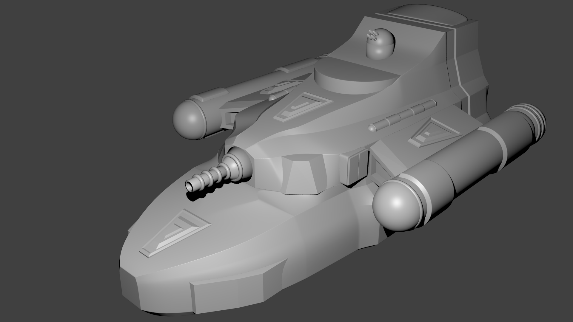
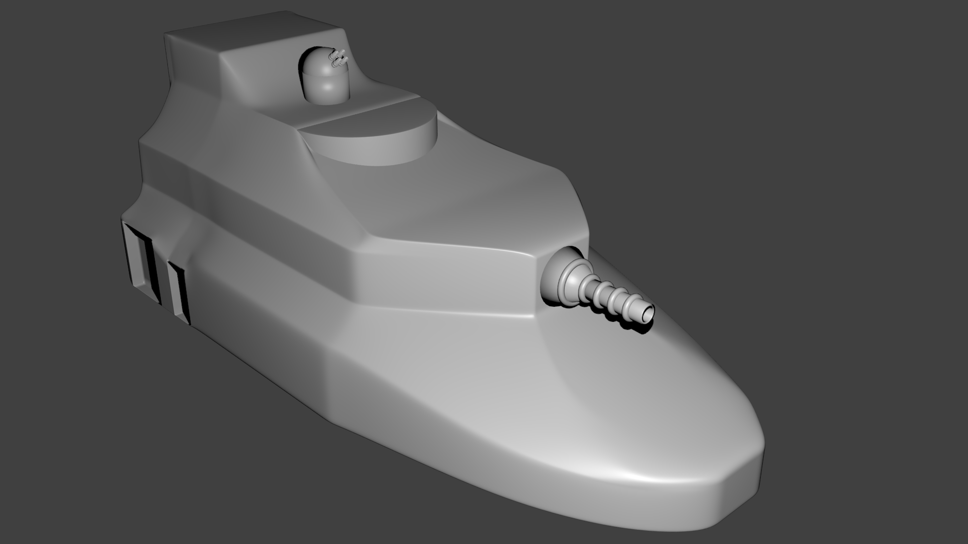
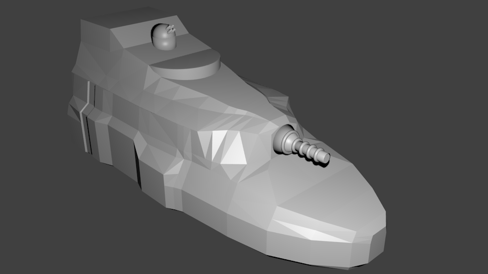
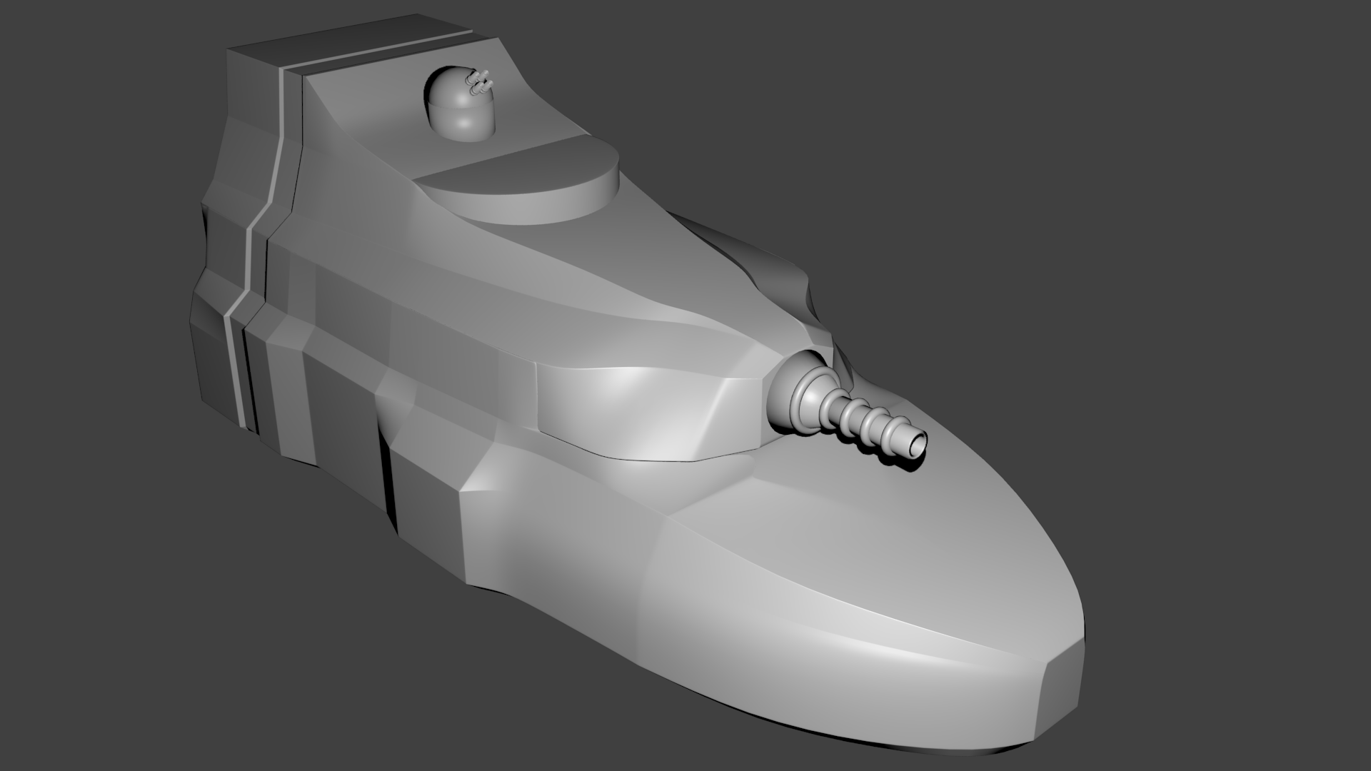
TV-04R Small Freighter
The TV-04R is a small early-model freighter from TransTravel. While not sleek or glamorous, it is a completely functional vessel. In the early days of of TransTravel’s history, they had nearly 100 of these vessels plying the spaceways. Mostly replaced by larger, more efficient vessels, most TV-04R freighters are at least a decade old and have been sold off to independent traders.
The ship is lightly armed with two laser batteries and can carry up to 50 cargo units (7500 tons) of material. Designed for a typical crew size of 6, it has an additional 6 berths that can be rented out at Journey class rates to those seeking passage on its route.
The TV-04R is not a speed demon but has two reliable Class B Ion engines to provide steady, worry-free operation. It is also not aerodynamic by any stretch of the imagination and its ion engines preclude it from landing on any planet with an atmosphere.
The full ship specs are:
Hull Size: 5 HP: 27 ADF: 1 (5 if no cargo) MR: 1 (5 if no cargo) DCR: 37 Engines: 2 Class B Ion Engines Fuel Capacity: 10000 fuel units per engine Accommodations: 12 Journey Class Life Support: – Primary: standard system – 12 beings, 200 days – Backup: standard system – 12 beings, 200 days Communication & Detection Equipment: Videocom radio (with a master and 3 secondary control screens), Subspace Radio, Intercom (2 master control panels, 30 standard panels, 15 speaker panels), Radar – Type I, Skin Senors, Camera system Computer Level: 4 FP: 102 Computer Programs: Ion Drives 4, Life Support 2, Alarm 2, Computer Lockout 4, Damage Control 2, Astrogation 4, Laser Battery 1, Laser Battery 1, Communication 2, Information Storage 2, Installation Security 3, Skin Sensors 1, Maintenance 2, Cargo Arm 2, Cameras 1 Ship’s Vehicles: small launch, small lifeboat Other Equipment: 2 cargo arms, complete backup computer Weapons: LB (x2) Defenses: RH Control Spaces: 8 Cargo Capacity: 50 cargo units (7500 cubic meters, 15000 tons) Volume: 10339 cubic meters (total), 2271 cubic meters (inhabited) Unloaded Mass: 3766 tons Loaded Mass: 18766 tons ADF per Fuel Unit: 1 (5 if no cargo) Crew Size: 8 Cost: new: 2,127,851 cr. (unfueled)
The ADF of 1 is the value when the ship’s cargo hold is fully loaded. Completely empty the ship can actually achieve and ADF of 5. Every 12.5 cargo units (3750 tons) of material transported reduce the ADF by 1 from the maximum of 5.
The ship available to the PCs is 14 years old and currently lacking the following items from the above description:
small launch
small lifeboat
both laser batteries
all life support supplies
In addition, the atomic fuel pellets for the ship’s two engines each need to be replaced (32,000 cr. each). Fuel for the ships ion engines is 17 cr per fuel unit.
Given the age of the ship and the lack of equipment, the ship is available for 1,580,552 cr.
I was going to post another ship next but realized that I should probably talk a little bit about the way I redesigned the engines in my new starship construction system. Otherwise, some of the bits of information about the ships won’t make sense. I’ve published some of this on-line before but I don’t remember exactly where so I’m repeating it here for completeness. Here is the section on engines from the starship construction system document.
Engines
Now that we know the mass of our ship, it’s finally time to
determine its propulsion. Each type and size of engine is rated to have a
specific thrust and fuel capacity. Your ship’s hull size determines the maximum
number of engines it can support. You don’t have to have to fill all your
engine slots if that number of engines is not needed to achieve the performance
you desire. And regardless of hull size
and engine type, the maximum acceleration of any ship is 6g.
Hull Size
Max Engines
1
1
2-4
2
5-8
4
9-12
6
12+
8
(Note: I didn’t even follow my own rules when I created the PGC C-10 Fast Courier as I gave it 4 engines at HS 4. This is something I’m still thinking about/working on.)
Engine thrust is given as an arbitrary thrust rating that has been scaled to work with the mass of the ship as given in tons. To determine the maximum acceleration of your ship, add up the thrust ratings of all your engines and divide that by the total mass of your ship in tons. The resulting number is the maximum acceleration of your ship in multiples of one standard gravity (10 m/s/s). Round all fractions down to the nearest tenth of a g.
Chemical Engines
These engines use a high efficiency chemical fuel that burns
and is expelled out the engine nozzle to provide thrust. These engines are relatively cheap and easy
to produce. While very powerful, because
of the large volume of fuel needed, these engines have limited capability in regards
to how long the engines can operate on a single fuel load. These engines are typically used for
ground-to-space shuttles and system ships.
Ion Engines
Ion engines work by ionizing hydrogen and accelerating the
resulting protons and electrons to high velocity and expelling them out the
back of the engine to provide thrust. Each
engine contains a small nuclear reactor to provide the power needed to ionize
the hydrogen and accelerate the particles to the relativistic speeds needed to
generate thrust. This reactor uses the
same atomic fuel pellet as an atomic engine but only needs to be replaced once
every 10 years. The initial fuel pellet
is included in the cost of the engine.
While not as powerful as chemical or atomic engines, Ion
engine fuel is relatively cheap and if a ship is properly equipped, can be
harvested from any gas giant for free.
Because of the nature of the engine, ships with ion engines
cannot land on or take off from planets.
Atomic Engines
An Atomic engine is a supercharged version of the chemical engine and uses the same fuel. The engine works by generating a quantum field that temporarily increases the momentum of particles by a factor of hundreds. These temporarily super-massive particles are ejected out of the back of the engine to generate thrust for the ship. Because each particle is effectively much more massive, less fuel is needed to achieve the same thrust and instead of a single fuel load lasting for only few minutes of thrust, it can last for days and allow the ship to accelerate to Void jump speeds.
However, generating this field requires a huge amount of
energy (which is transferred to the particles) during operation. To provide this power, each engine contains
its own nuclear reactor, similar in design to the reactor in the ion engine. However, the large power requirement of the
atomic engine means that it consumes one atomic fuel pellet after only 10,000
minutes of full thrust operations (about 8.5 days) instead of the 10 year life
span for the atomic fuel pellet in an ion engine.
In addition, atomic engines require an overhaul every few jumps, again depending on the size of the engines. This overhaul is necessary to make sure that the quantum field generators are properly aligned and positioned to only affect the fuel and not the body of the engine itself. The number of trips that a ship can go between overhauls depends on the size of the engine and is given in the table with the fuel costs below.
Engine Costs
The following table gives the cost and thrust values for
each of the different types and sizes of engines. Determine the number, size, and type of
engines your ship will use and then record the engines chosen for your ship.
Class A
Class B
Class C
Engine Type
Thrust
Cost
Thrust
Cost
Thrust
Cost
Chemical
6,250
50,000
20,000
175,000
80,000
770,000
Ion
3,000
100,000
10,000
400,000
40,000
2,000,000
Atomic
6,250
250,000
20,000
1,100,000
80,000
6,000,000
Fuel
Next you need to provide fuel for your engines and determine
how much acceleration each fuel load will provide for your ship. Each engine uses different types of fuel and
has different storage capabilities and requirements.
Chemical Engines
Each fuel load allows a chemical engine to operate at
maximum thrust for 60 minutes. This is
typically enough to allow the ship to make one round trip between the ground
and orbit or limited acceleration and maneuvering in space. Each engine can only hold a single fuel load
and must be refueled after each load is expended. The cost of a fuel load depends on the size
of the engine and is given in the following table.
Engine Class
Cost of a fuel load
Class A
300 cr
Class B
1000 cr
Class C
4200 cr
Ion engines
Although not as powerful as chemical or atomic engines,
these engines are reliable and can hold more fuel. While they can technically run off any
material, the fuel of choice is hydrogen.
Using any other fuel source decreases the thrust provided by the engines
by a factor of two. Each engine can hold
10,000 fuel units and each unit provides 10 minutes of operation at maximum
thrust (A fully fueled ion engine can operate continuously for over 80 days
without refueling). A fuel unit costs 5,
17, or 70 cr per unit for Class A, B, or C engines respectively.
Once every 10 years, the atomic fuel pellet in the ion
engine’s reactor needs to be replaced, the cost for this fuel pellet is the
same as that for a similarly sized atomic engine.
Atomic engines
Like the other engines, Atomic engines store all their fuel
internally. The fuel for these engines
consists of two parts. The first is a
load of fuel like the chemical rockets, the second consists an atomic fuel
pellet (typically uranium) to power the reactor. The amount of fuel that can be
stored depends on the size of the engine and is given in the table below.
Each atomic fuel pellet and load of chemical fuel provides
enough fuel for 10,000 minutes (about 8.3 days) of operation at maximum
thrust. The cost of a fuel pellet
depends on the size of the engine, given in the table below. The cost of the chemical fuel is identical to
that of the chemical engines of the same size.
Consult the table below to determine the number of fuel
loads & pellets held and time between each overhaul for each engine size.
Engine Class
Trips between overhauls
Maximum Fuel Loads & Pellets loaded
Cost per pellet (cr)
Class A
1
3
10,000
Class B
3
6
32,000
Class C
10
12
125,000
Compute total acceleration per fuel load
Acceleration is measured in ADF. One ADF is defined as 10 minutes of acceleration at 1g. (For you Star Frontiers grognards out there, I’ve redefined the boardgame hex scale to 3600 km so that 1 ADF does equal 1g acceleration for 10 minutes, and 1 g is defined as 10 m/s/s not 9.8.)
If you want to keep it simple, you can simply assume the
following:
a load of fuel in a chemical rocket provides
just enough thrust to make one round trip between the ground and orbit around a
planet or can provide a total of 8 ADF in space.
Ion engines use one fuel unit per engine per ADF
and a total of 1000 fuel units per engine for a single interstellar jump
Atomic engines use one chemical fuel load and
one atomic fuel pellet for a single interstellar jump or the same fuel provides
enough thrust for a total of 1000 ADF if operating solely in-system.
If you want to be a bit more exact and track the exact fuel
usage you can do the following to compute the total number of ADF that a load
of fuel will provide for your ship. This
will depend on the type of engine you have.
It requires more bookkeeping but actually results in less fuel being
needed in the long run, sometimes significantly if the ship has a high maximum
ADF.
Chemical Engines – Take the maximum acceleration you calculated for the ship earlier and multiply it by 6. This is the total number of ADF your ship gets from using one load of fuel in each engine.
Ion Engines – The maximum acceleration calculated above is the number of ADF provided by expending a single ion fuel unit in each engine.
Atomic Engines – Take the maximum acceleration calculated earlier and multiply by 1000. This is the total ADF provided by using one unit of chemical fuel and one atomic fuel pellet in each of your engines.
Round all fractions down.
Assume that that small difference is used up in minor station keeping
and maneuvering
Examples
Chemical Engine
Fully loaded a Digger Shuttle (HS 2) has one Class A
chemical engine and a maximum acceleration of 4.7g. Since it has chemical engines, the total ADF
provided by the single load of fuel in its engine is 4.7 x 6 = 28.2 or 28
ADF.
Ion Engine
A small (HS 7) freighter is equipped with four Class B ion
engines. Fully loaded, its maximum
acceleration is 1.1g. Thus by using up
one fuel unit in each of its four engines, it has 1.1 ADF available. If each engine carries it’s maximum fuel load
(10,000 units each), the total ADF available to the ship is 11,000 ADF. Since each interstellar jump typically takes
1000 ADF to complete, the ship can make 11 trips without refueling if it needed
to.
Atomic Engine
The newly designed Swift class assault scout has a total
mass of 2470.83 tons and two Class A atomic engines for a total thrust of
12500. This gives a maximum acceleration
of 5.059g which rounds to 5.0. The total
ADF available to the assault scout from one load of fuel in each engine is
therefore 5×1000 = 5000 ADF. After
expending this much thrust, the assault scout will have used two loads of
chemical fuel and two atomic fuel pellets, one in each engine.
As I mentioned in my last post, I’m in the process of setting up a play-by-post game and the players want to be a group of adventurers with a ship that knock about the Frontier doing odd jobs and generally getting into and out of trouble. As part of that I want to give them a few choices of ships that they could start with. So for the next few posts, starting with this one, I’ll be presenting the ships I’m designing for the adventure.
While these are specifically designed for Star Frontiers, they could easily be adapted to other systems. Each of these ships is being designed with some new starship construction rules that I’ve been working on. The rules are designed to be a drop in replacement for the existing Knight Hawks construction rules but more flexible and a bit more grounded in physics.
In these posts, I’ll just be presenting just the stats for the ships and a brief description. I’ll probably go back and create detailed deck plans for them at some point starting with whichever ship the PCs decide on buying with their starting fund. I might even do a 3D model.
So with that introduction, lets get to the first ship.
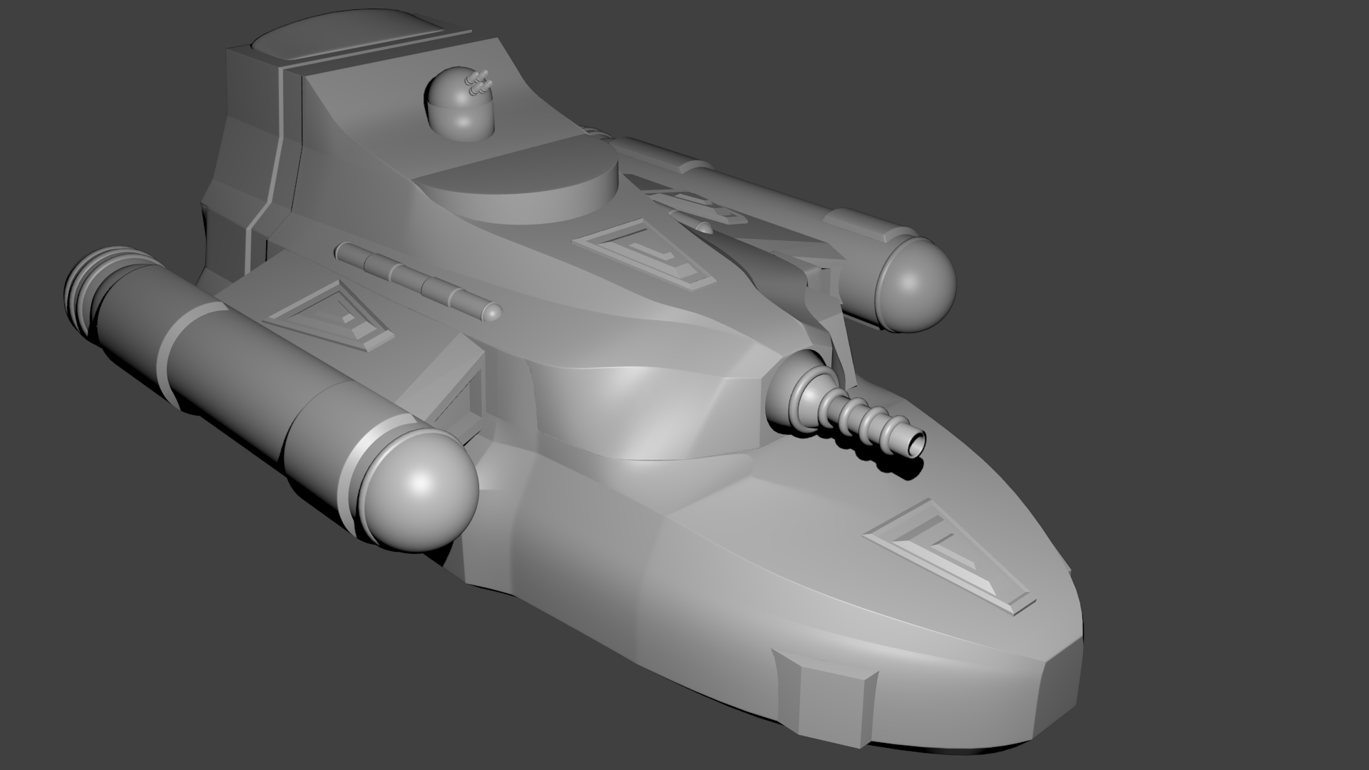
PGC C-10 Fast Courier
The C-10 Fast Courier is a small, hull sized 4 vessel that is aerodynamically streamlined and capable of planetary landings. Designed to be a fast transport ship, it can carry cargo, passengers, or both and evade most pursuit. Lightly armed with two laser batteries, it also carries four ICM salvos and a pair of decoys to help it evade pursuers.
The full ship specs are:
Hull Size: 4 HP: 21 ADF: 4 MR: 4 DCR: 35 Engines: 4 Class A Atomic Engines Fuel Capacity: 3 full loads per engine Accommodations: 2 First Class, 10 Journey Class Life Support: – Primary: standard system – 10 beings, 200 days, deluxe – 2 beings, 200 days – Backup: standard system – 10 beings, 200 days, deluxe – 2 beings, 200 days Communication & Detection Equipment: Videocom radio (x2, each with a master and two secondary control screens), Subspace Radio (x2), Intercom (3 master control panels, 30 standard panels, 15 speaker panels), Radar – Type II, Energy Sensors – Type I, Skin Senors, Camera system Computer Level: 4 FP: 164 Computer Programs: Atomic Drives 4, Life Support 2, Alarm 4, Computer Lockout 4, Damage Control 4, Astrogation 4, Laser Battery 1, Laser Battery 1, ICM 3, Communication 2, Information Storage 2, Installation Security 3, Robot Management 4, Skin Sensors 1, Maintenance 2, Cargo Arm 2, Cameras 1 Ship’s Vehicles: small launch, small lifeboat, 2 escape pods Other Equipment: cargo arm, complete backup computer Weapons: LB (x2) Defenses: RH, ICM (x4), Decoy (x2) Control Spaces: 10 Cargo Capacity: 10 cargo units (1500 cubic meters) Volume: 4955 cubic meters (total), 2764 cubic meters (inhabited) Unloaded Mass: 2728 tons Loaded Mass: 5728 tons Crew Size: 8 ADF per Fuel Load: 4364 Cost: new: 2,548,731 cr. (unfueled)
The specified ADF of 4 is for the ship fully loaded. Unloaded, the ship would actually be capable of and ADF of 9 but is limited to a maximum of 6 due to the limits of the PCs’ physiology. It can achieve this higher ADF of 6 as long as it is carrying 1400 tons (4.7 cargo units) or less of cargo.
The ship available to the PCs is 26 years old and currently lacking the following items from the above description:
small launch
small escape pod
one laser battery
all life support supplies
both decoys
all ICM missiles
Given the age of the ship and the lack of equipment, the ship is available for 1,597,460 cr.
I was going to start posting the designs for some new starships for Star Frontiers. However, since I’m building them with my custom starship construction system, I realized that some of the bits of information won’t make sense for those that are familiar with the standard system.
I’ve been working on this system off and on for years but it’s finally at a point where it is usable. While it’s possible to generate all the ships from the standard Star Frontier system, this system is a bit more flexible and allows for a wider range of ship designs. And the ships created can be dropped directly into the existing game alongside existing ships. At least in terms of boardgame statistics. The sizes of the ships are somewhat different.
So before I start posting the new ships, I thought I should at least provide an introduction to this new system. And I’ll do that by simply posting the Introduction section from the new rule system. I’m working on polishing this up and will be releasing it sometime in the future.
Knight Hawks Starship Construction 2.0
This is an alternate ship construction system for the Star
Frontiers RPG. While all the components
are the same as in the standard Knight Hawks rules, this system takes a more
realistic approach to the construction of the starships that is based on the
volume and mass of the ship’s components.
While the original Knight Hawks system is based on picking a hull size
and then limiting what the ship could do based on that, in this system you pick
the components of the ship based on what you want it to do and the capabilities
and performance you want it to have. The
hull size is then just a function of the ship’s systems.
From the perspective of both the Knight Hawks board game and
general role playing, the resulting ships are nearly identical to those
generated with the original Knight Hawks system. The differences are mainly in size and cost.
The main differences are as follows:
Life support systems have more variety, are more detailed, cost more, and are bulkier than in the Knight Hawks rules. They also scale more realistically as you increase the number of beings supported.
Hulls have more variety and are more expensive. In addition to the standard hull, we introduce three additional hull grades that have varying cost, mass, and hull points. Instead of the cost of the hull scaling linearly with the hull size of the ship, it now scales with the volume of the ship.
Engines are more appropriately scaled. Each engine type and size now has a thrust rating. This, combined with the mass of your ship, gives you the acceleration that the ship can achieve. The engine classes are scaled appropriately to provide proper amounts of thrust to move the bigger ships. The costs are also scaled appropriately to the thrust provided by the engines. Fuel costs also scale with engine size.
These ships are more expensive. This is primarily due to the changes in the cost of hull, engines, and life support. All three of these systems are more (and in some cases much more) expensive than the same systems in the Knight Hawks rules. This was done for a variety of reasons but primarily to make the costs scale realistically with the size and capability of the systems as they grow larger.
Hull size is computed a little differently. While it still scales exponentially with the volume of the ship, it has now been modified so that the hull size and volume are mathematically related instead of being arbitrarily scaled. This has the result of making the smaller hull sizes larger than the corresponding hull size from Knight Hawks while the larger ships from this system are actually smaller than a ship of the corresponding hull size from the original rules. For example, an average HS 1 ship in the new system is 64 cubic meters in volume which is double the size of a HS 1 ship in the original rules. And HS 1 in this system goes up to 216 cubic meters which is nearly half the size of a HS 2 ship from the original. On the other end, an average HS 20 ship in the new system has a volume of 512,000 cubic meters which falls between HS 11 and 12 in the original Knight Hawks system. [Note: This is something I’m not completely happy with and am still working on.] Additionally, there is no upper limit on hull size. You can build your ship as big as you have the budget for.
One final difference is that the definition of a cargo unit has been standardized to a specific volume. This is more realistic than the Knight Hawks system of one cargo unit per HS since in that system you could increase the HS by 2 and double the volume but only increase the cargo capacity by 2 not doubling it even though the ship was vastly larger. This change eliminates that discrepancy. It also means that ships will have tens to hundreds to even thousands of cargo units of hauling capacity. A future work will redefine the cargo tables to give prices and volumes to work with this new system.
Unless otherwise described, assume that all systems are identical to the systems described in the original Knight Hawks rules.
So what will I notice in the new listings
All of the old bits of information about the ships are still there. What has been added are a few new descriptors related to mass, volume, and fuel consumption.
Now instead of just listing the hull size, the actual total volume of the ship is provided. There are two parts to this. One is the overall volume including the cargo areas if any, and the other is the “inhabited” volume, or the part of the ship where the crew lives and works that doesn’t include the cargo hold. For vessels that are not primarily freighters these numbers are nearly identical.
In addition to the total volume, the mass of the ship, in tons, is provided. Again this has two values, one for the ship with the cargo areas empty, and another for the ship with a full hull (which assumes 2 tons per cubic meter of cargo). The ship’s ADF value is computed based on this full-loaded mass volume. For most ships there isn’t a different between that and the unloaded value. This isn’t true for freighters as unloaded, their engines can move the ship at much higher accelerations.
Finally, each listing provides a values labeled “ADF per fuel load”. This value represents the total number of ADF that can be achieved by fully burning through a load of fuel in all of the ship’s engines and is related to the fully loaded ADF value. These ships are actually more fuel efficient than in the original rules. It takes 1000 ADF to make an interstellar jump (and stop at your destination). Since most ships can run at an ADF of 2 or more, they only need a fraction of their fuel to reach jump speed and thus can make multiple jumps on a single load of fuel as long as they don’t run into trouble along the way and have to do a lot of maneuvering.
Playtesting
These rules are definitely a work in progress. I’m starting up a play-by-post game that will involve a lot of ships and traveling so I plan on testing these rules out extensively during that game.
That’s the basics. For my next few posts I’ll be sharing some ships that the PCs will have the option to buy as their starting vessel in that play-by-post campaign that are designed using this new system.
In part 2, we ended with the final version of the hull model for the Scavenger Transport and all that was left was to add in some of the details, most notably the doors and other bits that extended through the hull. After that, it is just “decorations” to add a little character.
Finishing the Physical Model
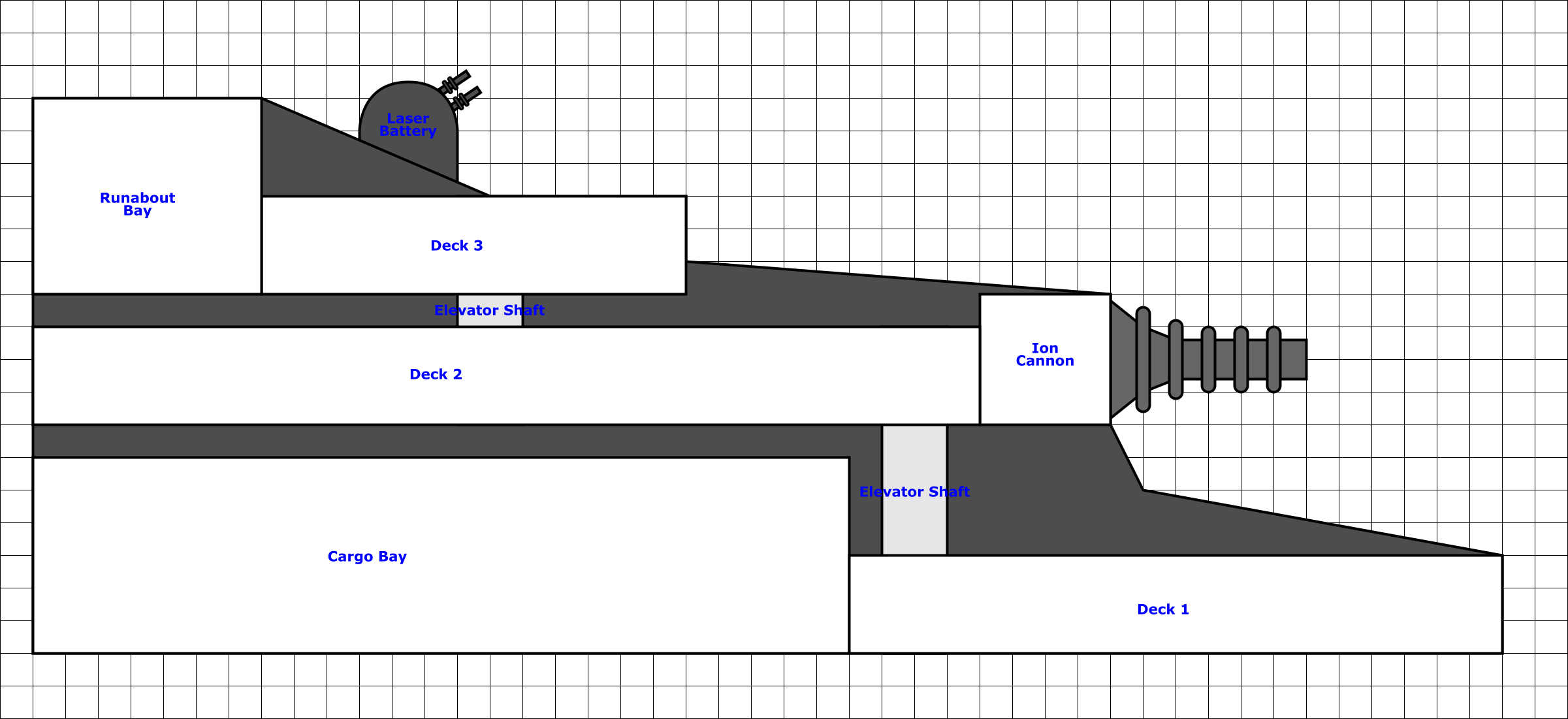
Adding in the bay doors was straightforward. They are just basically rectangles after all. For the smaller shuttle and workpod bay doors toward the back on the lower level, I added a split vertically down the middle for the doors to open and swing outward on the sides. For the larger cargo and runabout bay doors, I decided that they would open top and bottom so the seam detail runs horizontally. In the case of the cargo bay doors, the lower portion of the door can double as a loading ramp if necessary.
Next I wanted to break up the hull a bit so it wasn’t so plain and I created a little triangular design that I placed on the lower and middle decks for and aft of the ion cannon as well as on the wings. I then added a cylindrical structure on either side of the second level. Next, I added a bit of a domed structure on top of the runabout bay. Finally I created some large (2m diameter) portholes and placed them on the back of the ship on deck two between the cargo bay and runabout bay. These are positions to be in the rec room at the back of that level and the two cabins back there as well.
Back of the ship with the bay doors and portholes. You can also see some of the other details mentioned earlier.
At this point I was looking at the model and thinking it was looking pretty good and then I realized: I forgot to add in all the bits and pieces that stick out through the hull! Again these were fairly straightforward as they are fairly simple shapes. I tweaked the block that was the sensor array extension as it was sticking too far out. The rocket launcher (deck 1, starboard side) may get some tubes added to it for the missiles to launch out of in the future, but for now, I just left it as a solid block. I also rounded the edges of the airlock a bit.
Speaking of the airlock, after adding it in, I realized it was really poorly placed. It’s right up against the wing and behind the front part of the engine. Luckily the wing didn’t overlap it at all. I didn’t even consider it’s placement when I made the wing so I was lucky I didn’t have to go back and tweak that. It probably would have been better to put it on the lower level toward the front of the ship. I guess the engineers weren’t thinking too hard about how the engines were going to be placed when they designed the fuselage :-). However, its poor placement gives a bit of flavor and something to hassle the crew with (and for them to grumble about). It truth, it’s more of a backup measure anyway since the ship isn’t designed to actually dock at stations but rather pull up next to them and transfer via the shuttles and open cargo bay doors. So in practice it’s only a minor annoyance.
Once I had these last structures added, the ship was all done.
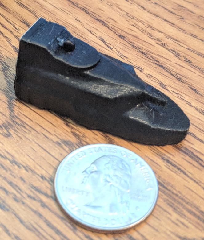
3D Printing
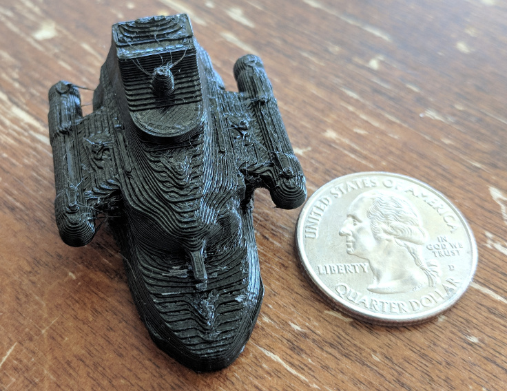
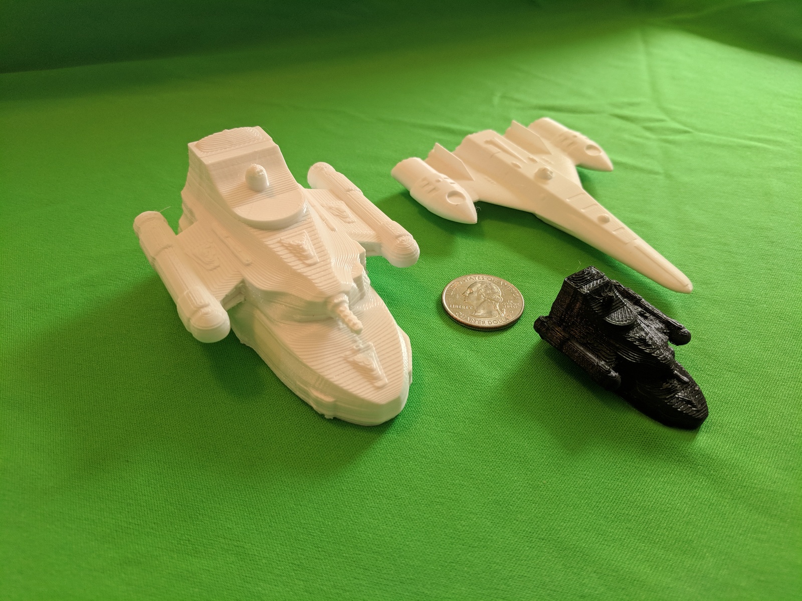
With the physical model done, it was time to start testing out 3D prints. I started with a simple small, low resolution print. This was done at 0.2mm/layer and at the native scale of the model (1/1000 scale). It only took about 50 minutes.
You can definitely see the print layers on the model. There are also hints of the details on the body, wings and engines although the size of the features are such that they just don’t show up at at this scale. This particular print was done with the bottom of the ship on the build plate. That may not be the best way to print as we’ll see in a minute.
Since it look good enough small, it was time to scale it up. The next print was a 1/500th scale print, double the size of this one. Again I printed at 0.2mm/layer and with the bottom of the ship on the build plate. Although this time I switched to white plastic. Here’s a picture of that print, together with the smaller black print, our trusty quarter, and a Star Frontiers Assault Scout model at the same scale as the larger print. This print took about 5 and a half hours
If you look closely at the larger print, you can still see the layer lines although since the print is bigger, they are not as pronounced. You can also see the turrets on the laser battery print at this scale. They were just too tiny to print on the smaller scale. You’ll also notice that the assault scout model in the back looks super smooth. That is because it was printed at 0.1mm/layer and was printed standing up.
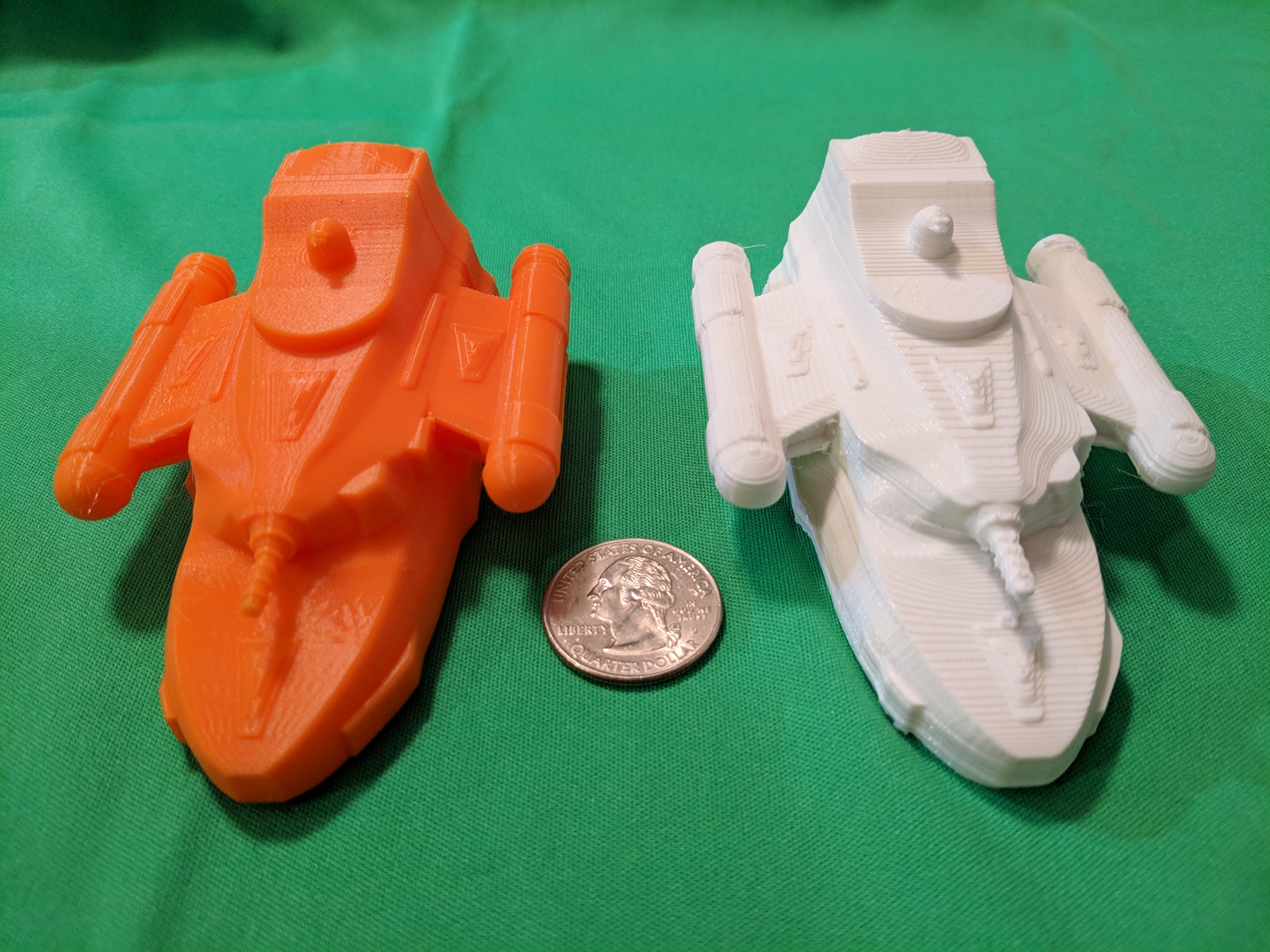
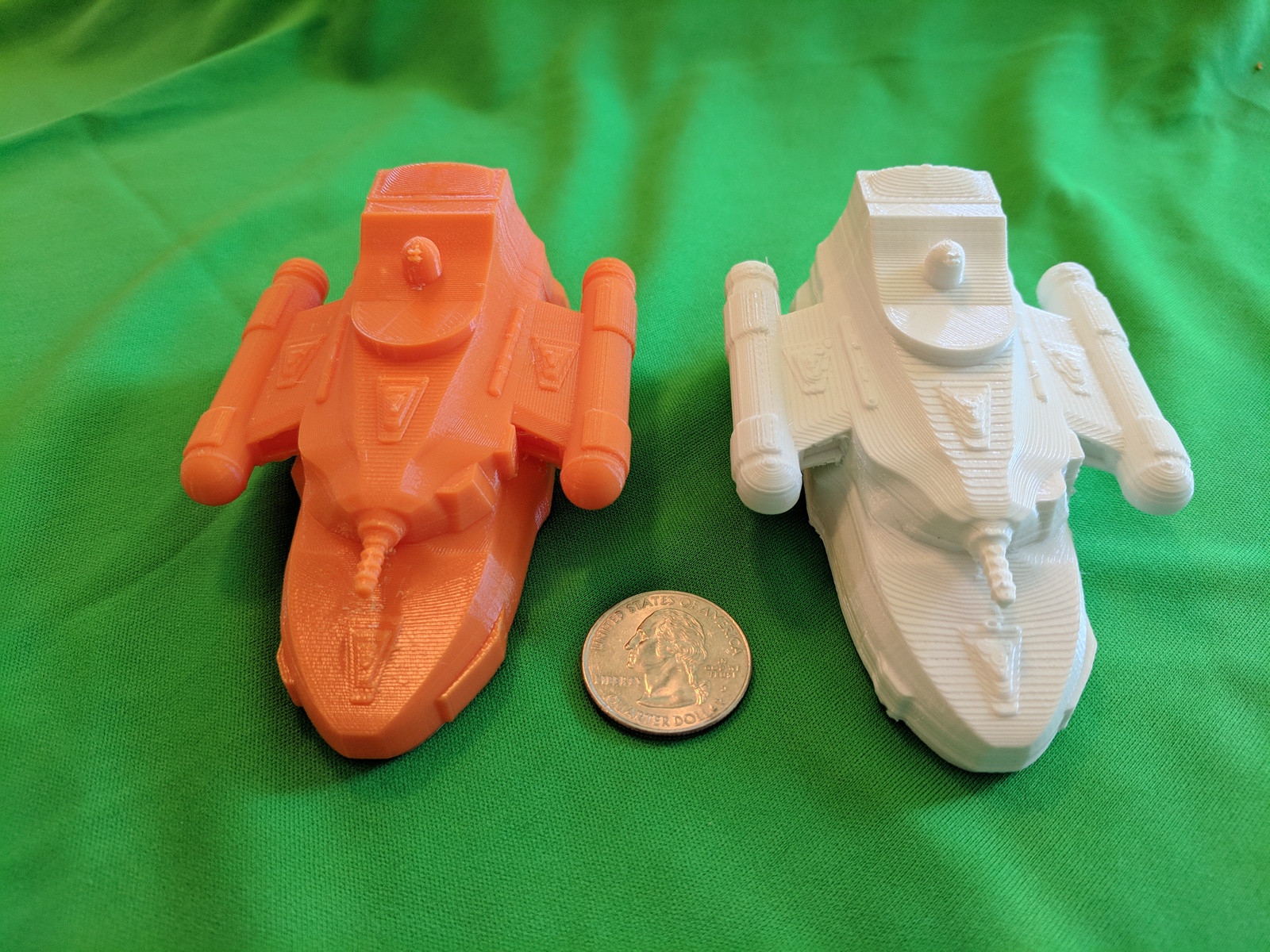
So that’s the next thing to try. My 7-year-old son really liked the ship and wanted an orange one (that’s his favorite color). Since I have a spool of orange filament for my printer just to print things for him, I swapped out the white for orange, flipped the model on it’s back, and started a 0.1mm/layer print. Here is the result, five and quarter hours later:
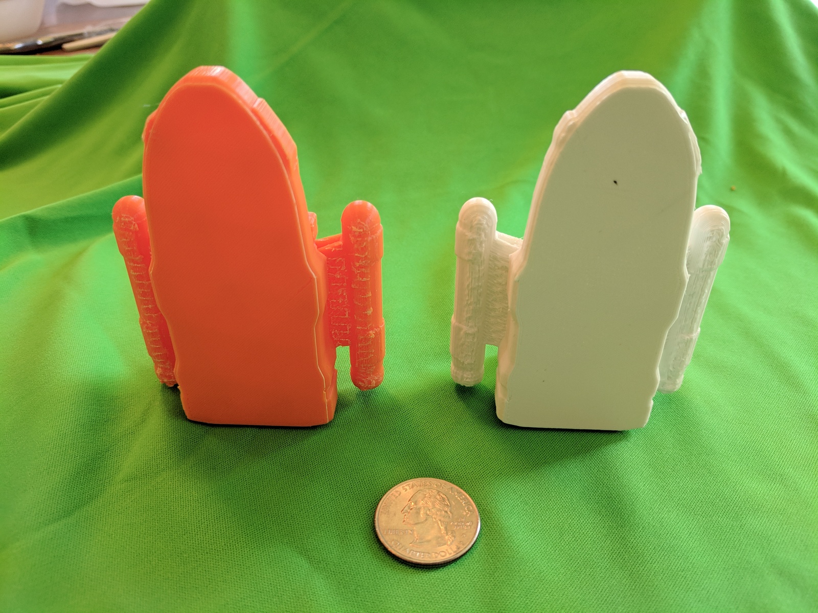
The surface on this one is much cleaner. That is partially due to the smaller print layers and partially due to the orientation of the layers relative to the model, but more of the latter. A 0.2mm print in this orientation would look pretty good too. The bigger difference, however, is the backs and undersides of the models. Let’s take a look at those. Here are the undersides:
The lighting could be better but you’ll notice that the bottoms of the wings and engines on the white model are really rough. That is partially due to the fact that I didn’t completely clean them up but also due to the nature of 3D printing. Since each layer has to be placed on the layer below, if you have a floating bit of your model with nothing under it, the printer prints support material to get up to that that point where it can start printing the model. So in the white model, a bunch of support material had to be printed to support the engines and wings. Most of that will clean off with some effort using an sharp knife and sandpaper (and my Dremel) but it’s not completely clean. On the orange model, we don’t have that problem and the engines and wings look really good and there was nothing to remove. However …
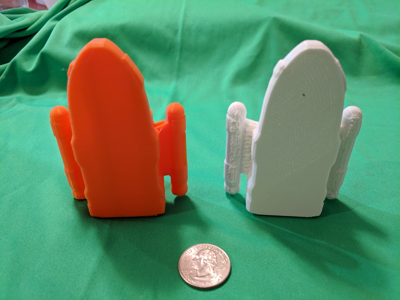
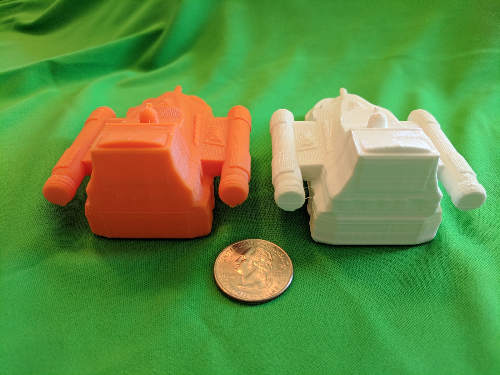
the back of the orange print has some issues. Granted the back of the white one isn’t the best, as you can see some issues with the layers of the print being slightly misaligned (I need to re-tighten the belts that drive the print head or slow down the print). However, you can see the detail of the bay doors and the portholes (barely, they should probably have been a bit thicker for printing).
On the orange print, this was the side toward the build plate and so had to have supports to the parts of the model that were suspended. In this case that is the back of the engine and wing as well as parts of the back of the ship. The bits on the engine and wings again are not completely cleaned up but they are flat surfaces in is orientation and much smaller surfaces as well. They will be much easier to clean up than the rough sections on the white print.
The back of the ship is a different matter. The surfaces of the cargo and runabout bay doors were the only parts actually touching the build plate. The rest of the back of the ship and the portholes were raised slightly. Because of that the printer had to lay down support material. However, because they were only slightly raised (like one or two 0.1mm layers), there really wasn’t that much room to print support material and it is all fused together. It could probably be cleaned up with some work but it would be pretty tough.
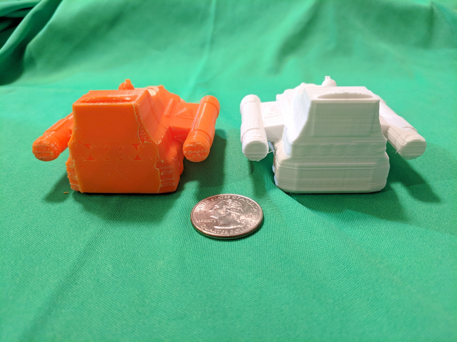
Finally I did a last print at the higher 0.1mm/layer resolution with the ship on it’s bottom (same orientation as the white print) just so see how that higher resolution affected the look.
As you can see, the to surfaces are much cleaner in this print. In fact, I would be very satisfied with that print surface on the model. Here’s the bottoms and backs:
Those bottom surfaces are still fairly rough although I think they are better on the higher resolution print. The back of the higher resolution print is definitely cleaner.
I think the print with the ship on it’s back is still the better way to go, but barely. It’s a tough call and I could be convinced otherwise. To address the problem with the support material on the back of the ship, I have a couple of options. One is to just remove all the surface features on the back of the ship completely. That would give a flat surface to print and would eliminate the problem but you would lose the details on that part of the unpainted model (you could always paint them back on). Another option would be to just eliminate the portholes. There is enough relief to the doors that you could trim the support material from around them. The rest of the back of the ship might be a bit rough but it is an easily accessible area to sand and clean up. The final option would be to increase the relief on everything, both the doors and the portholes, so that there is a bit more space there making the support material easier to clean off. I haven’t decided which route I’ll take yet but I’ll probably do some experimenting to try out the different options.
Going Forward
My Patreon supporters have already received a copy of the model file as it currently exists (that’s one of the perks of being a supporter). At some point I’ll put the model up for purchase for those that would like to get a copy (That will be on DrivethruRPG and either here or my New Frontier Games website). I’ll also make 3D printed models available. That will come once I’m comfortable with the way the prints are coming out.
The next step for the model is to back to the digital model and paint it so it can be used in 3D renders. I need to add textures and materials to the model to give it color and life. However, I’m going to put that bit on hold for bit as it’s not really needed for the module (and I want to go over the Blender tutorial on how to do all of that stuff. I have some experience from the assault scout but it was very trial and error). So this project will probably go on hold for a few weeks while I work on some other bits and pieces.
Bill is also working on the final versions of the deck plans and I’ll post a copy of those once they are available.
Let me know if you have any questions, comments, or suggestions below.
More progress on the ship model. If you haven’t read part one of this series, that describes how I laid out a model of the interior of the ship as a skeleton to build the hull around. In this post, I’ll actually start building the ship out. Let’s dive right in.
Try 1
I started by pulling the skeleton model I exported from OpenSCAD into Blender. The first thing I noticed is that Blender likes to work on really small scales. The model isn’t that big, only about 50mm long, half that wide and tall but it was was huge in the default view port. I had to zoom way back.
(If the text on that image looks a little small, that’s because its a screen capture of my entire 4k monitor’s screen. It’s a 43″ screen so I work at full resolution for maximum screen space.)
With that loaded, I can start forming the hull around it. It all starts with a cube. I created a cube the height of the cargo bay and then stretched, extruded, and molded it to fit around all the rooms and sections of the lowest level. Once that was done, I extruded part of the top of that level up to form the basis of the hull around the middle deck and then stretched and molded it to properly fit. Finally I did the same thing for the uppermost layer.
In modeling the hull, I had it extending out beyond the bay doors on the sides and back so that they were inset from the hull slightly. The circular bridge area on the upper deck was modeled as a separate piece.
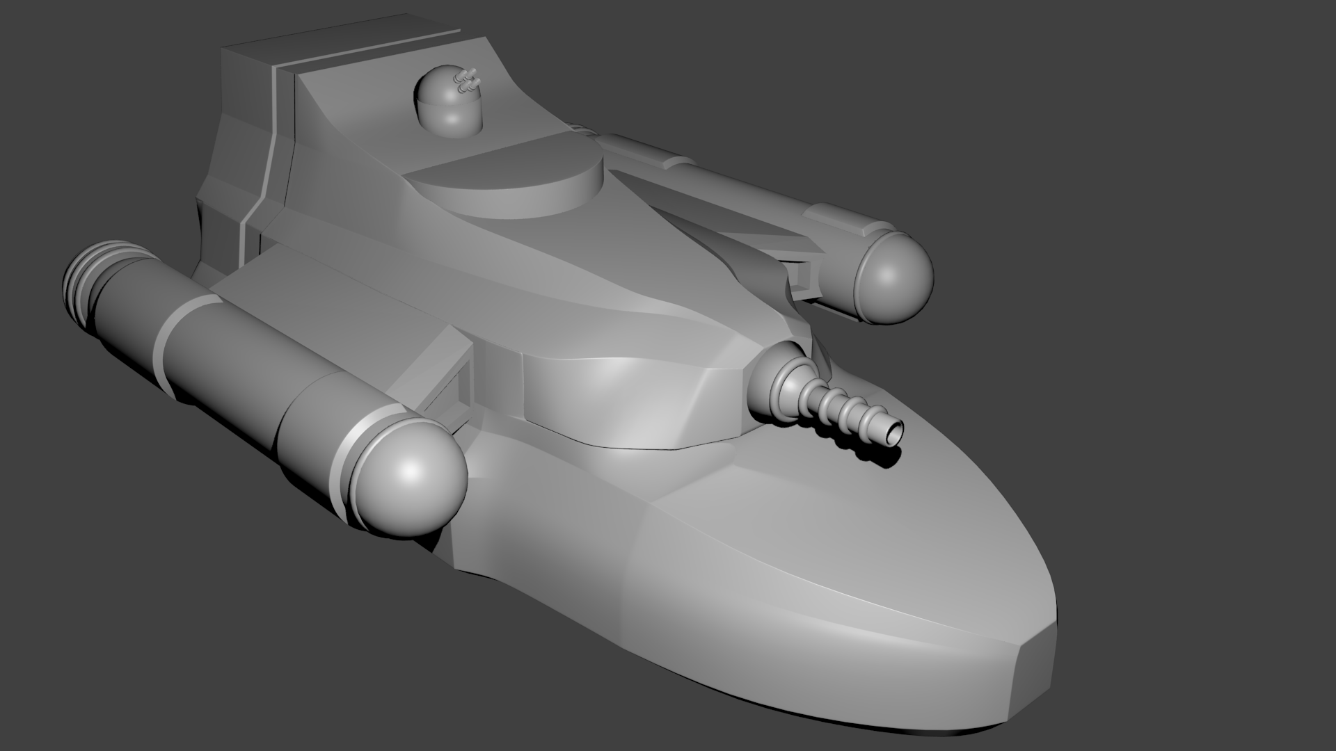
With the hull done, I created a model for the ion cannon and the laser battery and placed them in their appropriate positions on the model. When I was done, it looked like this.
It looks pretty good. But for some reason, I just didn’t like it. I think a big part of it was that it felt too smooth. I could have turned that down a bit but I still didn’t like the shape. There were bits of the hull that just looked weird up close and had somewhat strange geometries. One was the the bit of hull on the left and right side of the bridge “window” area. If you look closely at the image, you can see that it dips back down between the outer edge of the hull and the bridge proper. There were some other areas like that on the back of the ship and around the hanger bay doors as well.
So like all good prototypes, I threw it out and started over. The only thing I kept was the bridge, the laser battery, and the ion cannon.
Try 2
With a little more experience under my belt, I decided to start over and try again. I kept the original version around in case try 2 was worse but I didn’t expect it to be. This time around I decided that instead of trying to do the hull as a single piece of geometry, that I would break it up in to connecting pieces. While I had originally planed to do five pieces (one for each deck and two for the spaces between decks), I ended up only doing two overlapping pieces as you’ll see below.
This time around I decided to make the outer hull on the back and side be flush with the cargo, shuttle, workpod, and runabout bay doors. I’ll probably add a bit of overhang to those but that detail will be added to the exterior instead of built into the basic hull shape.
Again I started with the bottom of the ship. The process was the same but I made some different design decisions. I also was much more careful about coordinates when pushing, squeezing, extruding, and scaling parts of the hull. There were a number of times that I realized I had done something wrong and destroyed my symmetry. Each time that happened, I went back and fixed it. This is something that I didn’t do on the first attempt. I probably should have worked on just half the ship and mirrored it but it seemed to make more sense at the time to do it the way I did. (I also should have taken more screenshots as I was working on the model to show the stages but I didn’t. I’ll try to be better next time.)
Regardless, I created a lower deck model that I was much happier with than the first one. Once that was done, I started a second section of the hull and modeled everything on the second level except raising it to the full four meter height of the room containing the machinery for the ion cannon or the area that would connect the engineering spaces to the engines proper. The former would be done as part of the connection between deck 2 and 3 and the latter when I actually modeled the engines.
Once I was happy with the second deck it was time to connect the two. My original plan had been to created a completely separate piece of geometry to make the connection but sitting here with the two pieces in front of me, I decided to just extend the top of the lower deck and form it into the shape I wanted. So I extruded the bits under the second deck up and got to shaping the hull. In the end I didn’t just stop this modeling at the bottom of deck 2 but because of some of the feature that I wanted to continue extending, parts were modeled all the way up to the top of the second deck. Satisfied with that, it was time to move on to deck 3.
Again, the original plan was a separate piece of geometry but since this level was fairly simple, I decided to just extend the top of level 2 upward. I was several hours into the project at this point and feeling comfortable with the tools so it went fairly quickly.
Since the bridge area, laser battery, and ion cannon were already done, I just had to turn them on. Doing so made me realize that the area where the cannon was attached felt a little two boxy so I tweaked the design a bit there. I also needed to tweak the geometry around the bridge to expose a bit more of it. With that done, I ended up with this model for my second attempt.
You’ll notice that this one is much blockier than that first one. In that first attempt I had already applied some smoothing filters before exporting the image. I had not yet done so on this one and had first planned on leaving this one as is. I thought this looked pretty good so I even exported this as a 3D model and did a small test print.
I was quite happy how the print turned out. The barrels on the laser battery were too small to print at this scale (1/1000) but otherwise it looked pretty good.
However, looking at the actual model some more I decided I didn’t like it so faceted. Plus if you look at the back of the ship, there is that little bit of contouring that is pushing in a bit. That section fills the space between the doors for the shuttle and workpod bays. I decided that I wanted that to be a feature that ran all the way up the ship.
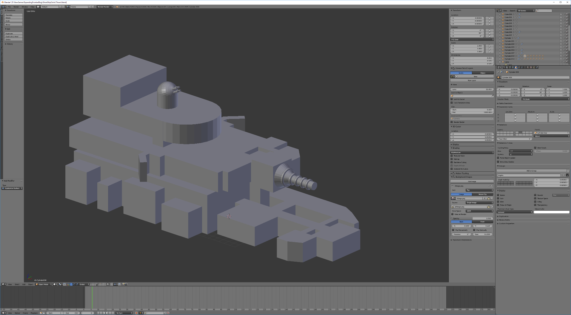
So I went back into the model and started tweaking. First I modified bottom part of the upper deck geometry to continue running that feature all the way up the aft portion of the ship. This was actually fairly easy as at this point in the ship, the outer edge of the hull is well beyond the interior walls. After that was added, I started smoothing out the surface and adding edges and features in where I wanted the model to have sharp edges. I ended up with the following model.
The one thing that adding the smoothing did was somewhat highlight the fact that it is two different pieces of geometry. You can see a slight seam between the two pieces in the area under the ion cannon. It runs around the front of the ship and back to the point just in front of the bulge mid-ship on the lower deck (that bulge is the location of the reflec screen on this side of the ship) where it turns upward to the top of the second deck.
This seam is not visible in the unsmoothed version as it is an artifact of the extra facets added to the geometry to make it smooth. It’s something I’ll need to clean up. I haven’t decided exactly how I’m going to do it but I have two options. One is to go in and tweak the geometry so that the two pieces (with the smoothing) line up better. That is actually what I did on the back half of the ship. You can’t see the seam back there. The other is to put surface details, such as pipes, equipment, etc. that run over that area of the ship to mask the region affected. It will probably end up being a combination of those options in the end but that is for later.
The other thing you can’t see in this image is that there is a bit of hull under the lower deck. It actually extends about a half a meter below the deck but it is beveled inward so it doesn’t really show up in the angle of this view. And the bit that is visible (just below the front of the bow and below the parts jutting out a little on the side) are in shadow from the lighting. This extension allows for some machinery and piping beneath the hull and the addition of landing pads as well.
Now that the outer hull is done, it’s time to add the engines.
The Engines
I didn’t really have any ideas for a design on the engines, I just knew they needed to be big and were going to be outboard on either side of the ship. So what I decided to do was use the engines depicted on that map at the end of the last post as a model. I imported that image into Blender to use as a reference and got to work. Here it is again.
I’m going to match the silhouette of those engines at the top and bottom. In this case, I am only going to model one engine and then mirror it to the other side of the ship.
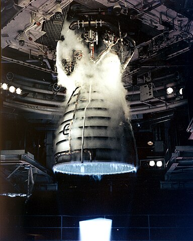
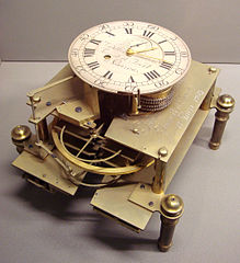
The engine design is fairly simple. It’s mainly a cylinder with a spherical cap at the front and an exhaust cone at the back. Plus some decorations along the side. I made a couple of variations on this image for the model. First, the exhaust cone at the back is symmetrical on my model I might go back and add that curve to it later but for now I left it alone. I also added some tori around the exhaust cone section of the ship reminiscent of the ribbing on current day rocket engines.
Image of the test firing of a Space Shuttle main engine. (click image to link to original on Wikimedia).
I also added one around the connection point between the cylinder and the sphere at the front of the engine (to mask the seam that shows up there when I applied the smoothing 🙂 ).
For those bits of geometry sticking out on the sides, I modeled them as extensions that ran a little more than half way around the engine instead of all the way around.
To connect the engines to the ship, I created some simple swept forward “wings”. All of these pieces were then smoothed and added to the model. With that done, I had the final model of the base hull ready to go.
What’s Next
Now that the base hull is done, it’s time to add the details. That will be the subject of the next post. First up will be those bits of the interior rooms that actually extend beyond the hull. On the side face in these images, the grapple launcher extends a bit out of the bow of the ship. On the other side we have the rocket battery launcher on deck 1 and the sensor array and airlock on deck two.
After that, I need to add in all the bay doors on decks one and three. That will complete the full basic structure of the ship. At this point I’m going to do another 3D print. At the small scale that I used for the first test print, that is all the detail that might show up. Any other smaller details would only show up on a larger print.
Once those final necessary features are added on, I’ll go through and add some other details and features to break up the completely smooth surfaces just a little as well as some recessed landing gear on the bottom of the ship. While the ship doesn’t normally dock or land on planets, it is capable of landing on smaller, very low gravity objects so I need to add that feature in.
So what do you think about the design? Any additional features you think should be included? Let me know in the comments below.
Now that the basic deck plans are done, I want to make a 3D model of the ship. I’m going to be posting this as a series of small articles as I work on the model so you can see the bits and pieces as they happen. Let’s get started.
I’m going to be trying something new for this model. Well, new for me at least. I’m going to attempt to create the model in Blender. I’ve used Blender a bit in the past but only to add materials and textures to an existing model that I created somewhere else. Never to completely create the model from scratch. In the past I’ve done all my models in another program called OpenSCAD. It has some features that I really like (as described in this post on the Arcane Game Lore Blog). But it also is fairly simple and I’d like to have the extra control an options available in Blender. If you want to see some of the other things I’ve created, check out the 3D Models category here on the Expanding Frontier. That includes several posts I’ve made on the subject.
So we’ll see how this goes. I’ve been working through a Blender fundamentals tutorial on Pluralsight and feel comfortable with the basics that I think I’ll need to create this model. If all else fails, I can fall back on OpenSCAD. In truth I’ll be using both of those tools in this project since I can export objects from OpenSCAD into Blender. So for parts and pieces that make more sense to create in OpenSCAD, I’ll be using that.
The Skeleton
For this ship, the first step was to lay out all the interior pieces in their proper size and position. This is what I’m calling the skeleton of the ship. Once that is done, I can build the hull around the interior structure so that it is all properly contained.
This is one of those cases where OpenSCAD is just going to be so much easier to use then Blender. Since we’re talking about adding in basic geometric shapes in very specific, defined positions, the programming interface to OpenSCAD that allows me to specify the position and dimensions of basic shapes like cubes, cylinders, and spheres is exactly what I need.
I work on these models at 1/1000 scale. The default units in OpenSCAD are millimeters so I just use the sizes of the rooms in meters as my values in the functions. This naturally gives me that scale. I can always scale it up (or down) later as needed. For tabletop minis to be used in a tactical game, I typically create the model at 1/3000 scale so I just have to scale the final model by 1/3. For display models, I can scale it to anything I want.
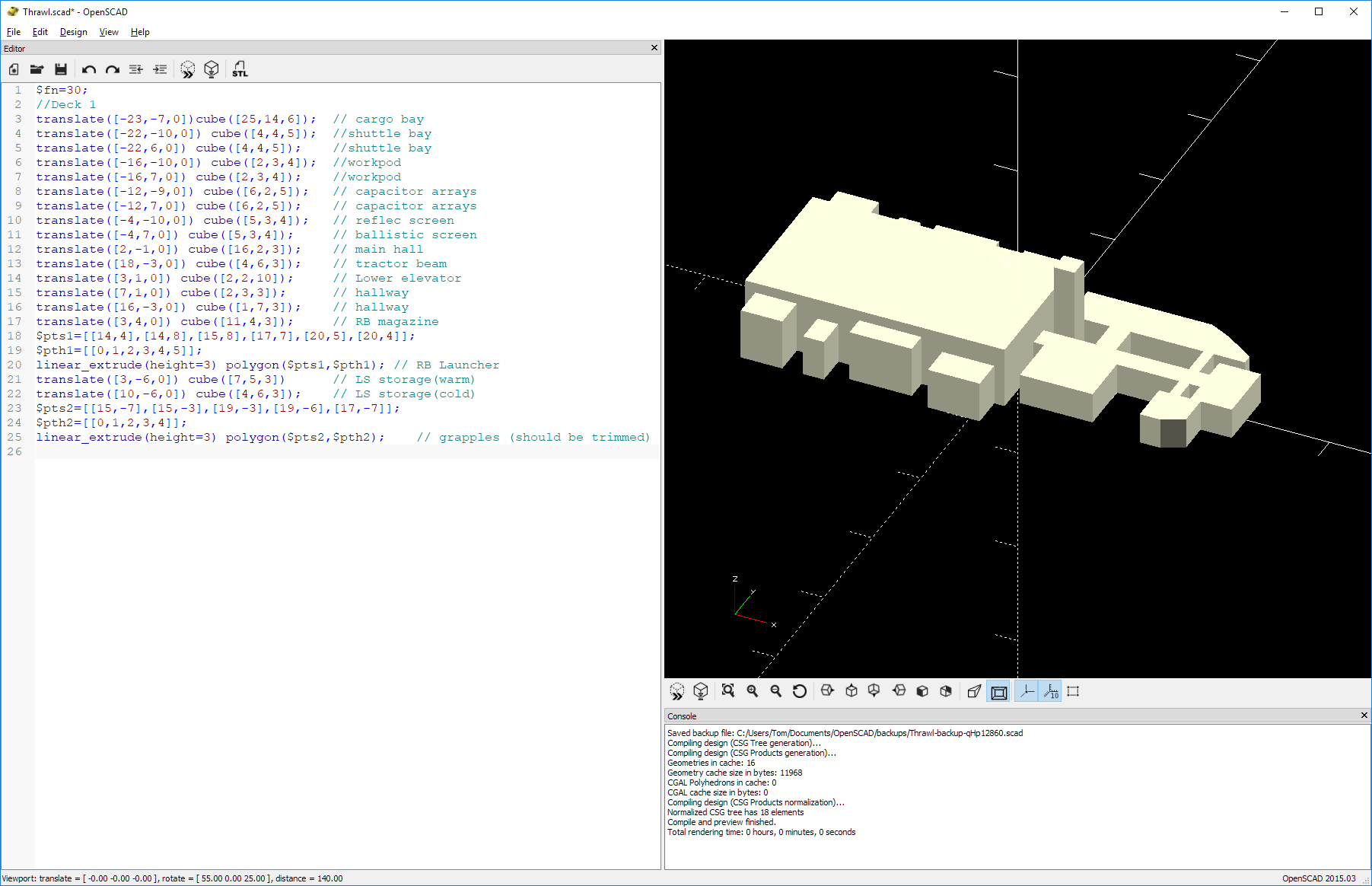
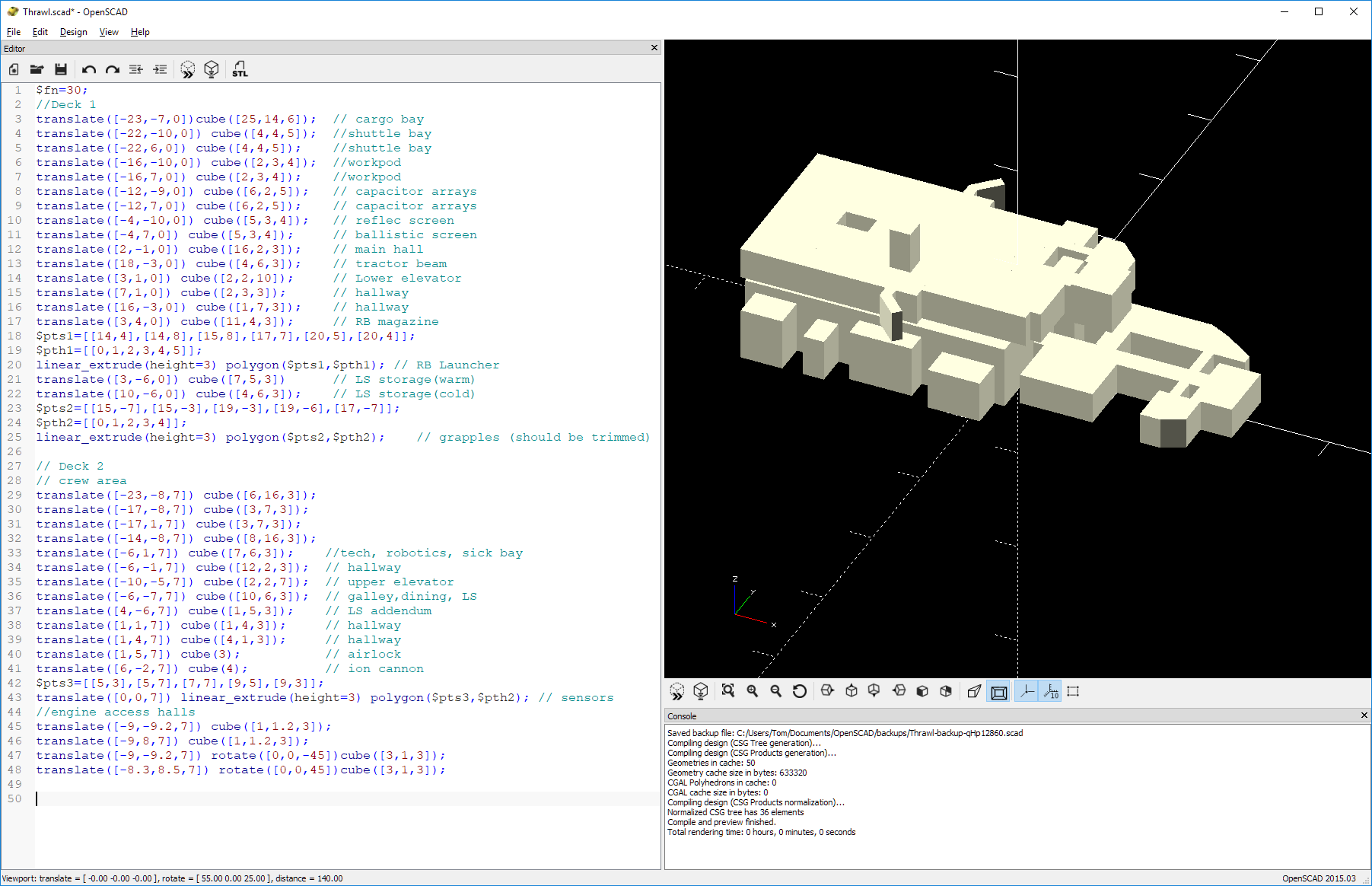
Deck 1
To begin, I just pulled up the deck plan for deck 1 (the lower deck, see this post) to use as a reference. OpenSCAD needs an origin so I selected the center of the grid to be (0,0) in the horizontal directions and the bottom of the deck to be 0 in the vertical direction. I could just have easily selected the lower left of the deck plan but thinking ahead, I knew I would want the origin on the center-line when I got into Blender so I chose appropriately. I then just started adding in boxes to represent the various rooms in the ship.
The cargo bay is 6 meters tall. The little side rooms off of it are not quite as tall ranging from 3-5 meters in height. The forward section of this deck has 3 meter tall rooms. And the elevator shaft connecting this deck to the upper one can be extended 10 meters up to intersect the middle deck. Here’s what things look like after adding in this first deck.
On the left is the OpenSCAD code. On the right is the actual render of the code as a 3D model. The large block sticking up high in the middle is the elevator shaft to the next level up.
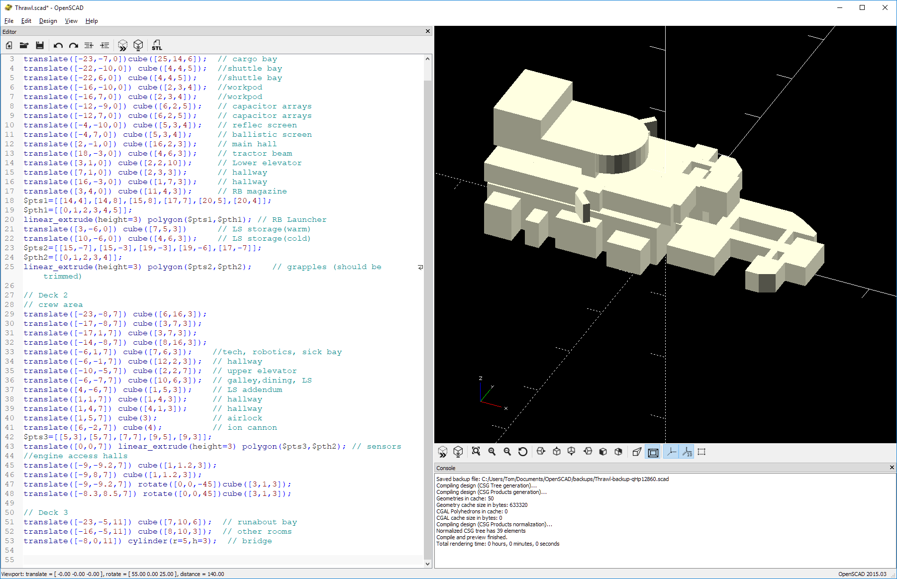
Deck 2
On the first level, I added in each room individually. On the middle level, there are a lot of rooms that are adjacent forming large blocks. These areas I just added as single large bits as there was no need to make them all individual. This model I’m creating is just really a sort of wire-frame and will not be part of the final model. It’s more of a guide. The room for the Ion Cannon machinery is 4m tall instead of the standard 3m and is so represented in the model. Here’s the model after this deck has been added.
Those little bits sticking out on the sides are the access tunnels to the engines. Those might very well change as I start modeling but for now, I’m just reproducing what’s on the sketches I drew. Somewhere out there will be engines. Again the bit sticking up is the elevator shaft to the next level.
Deck 3
Finally we need to add in the upper deck. This one has the 6m high runabout bay aft with all the other decks being 3m in height including the round bridge area. Again this deck has a bunch of adjacent rooms that form large blocks. In fact, it only took three shapes to model this: the large block for the runabout bay, a cylinder for the bridge, and an block connecting the two to represent the other rooms. Here’s the model with deck 3 added.
Nothing really exciting here. Although now you can see how the ship sort of tapers toward the middle and the back as you go up to the higher levels.
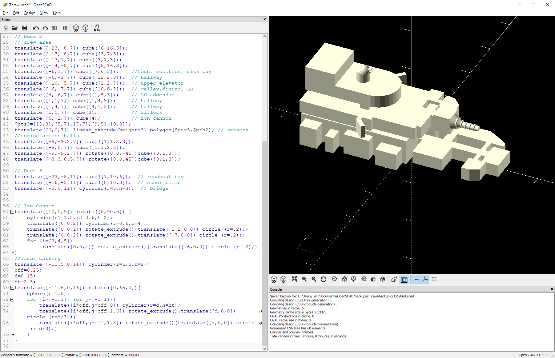
Weapons
Finally, I wanted to add in the exterior weapons: the Ion Cannon and the Laser Battery. So I went in and modeled those to scale and put them on the ship. Having these exterior elements will help me to get the hull placed properly. With the weapons added, I now have a completed model of the interior of the ship as well as some of the exterior features I need to account for. Here’s the final model.
Making the weapons was kind of fun. I may just export those out to use in Blender. It depends on how hard it is to make the tori around the barrels.
And Done (for now)
Now that the model is done, I can create an actual 3D object and export it for use in Blender. That’s it for this segment of the modelling process. Next time I’ll pull this skeleton model into Blender and start shaping the actual hull around it.
Let me know if you have any questions, comments, or suggestions in the comment section below.
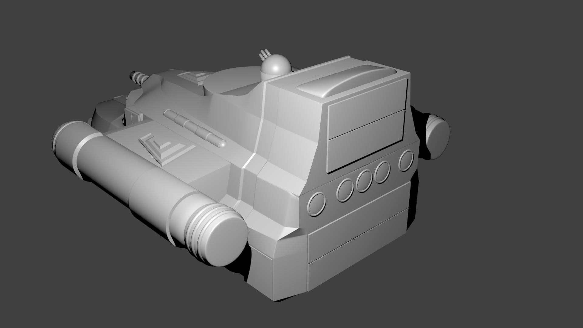
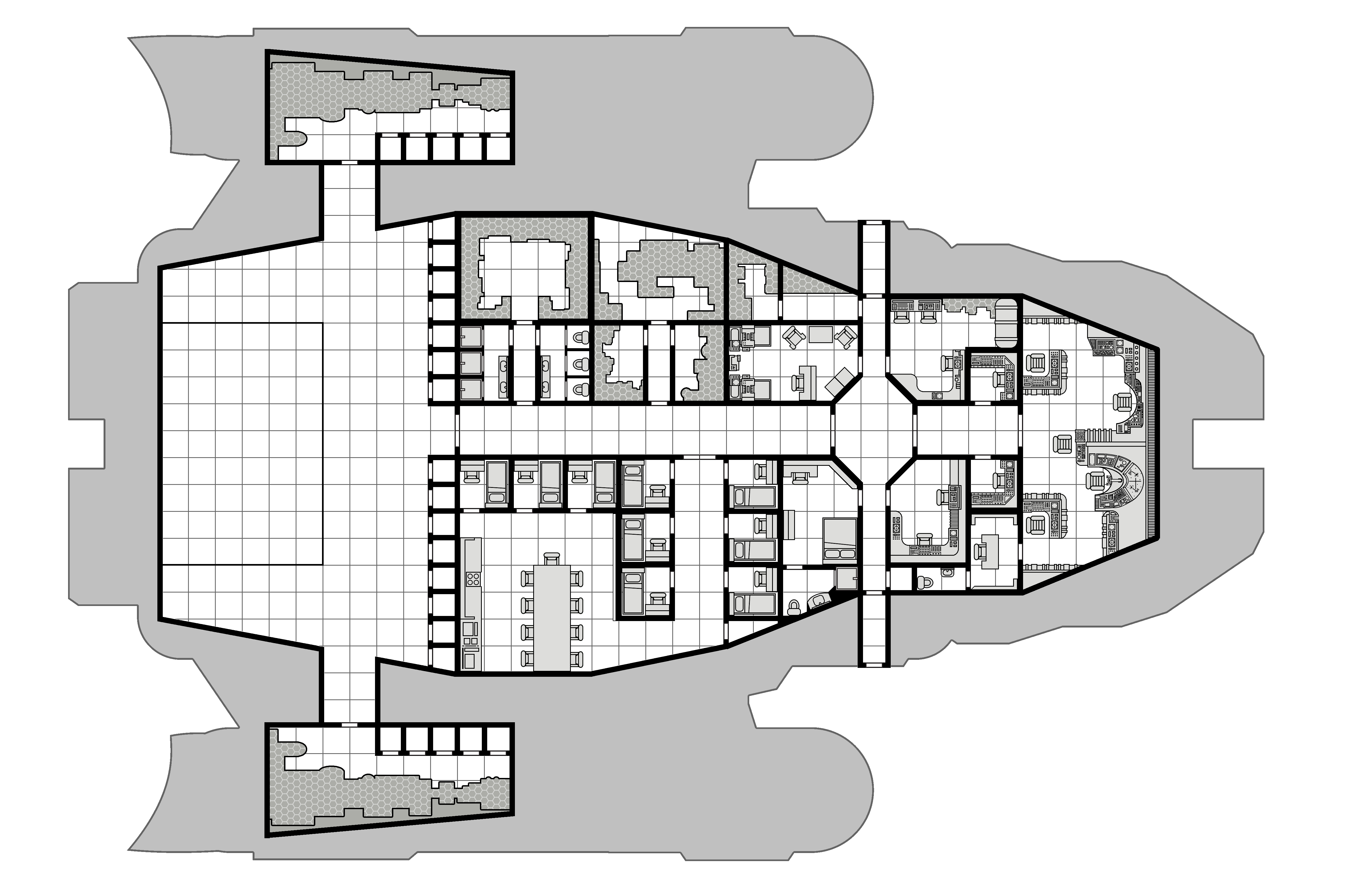
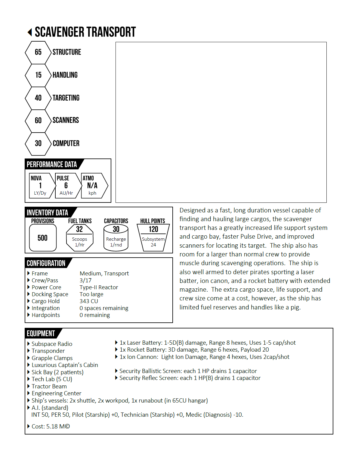
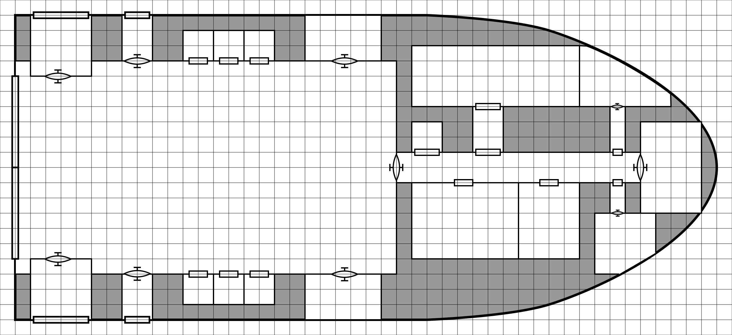
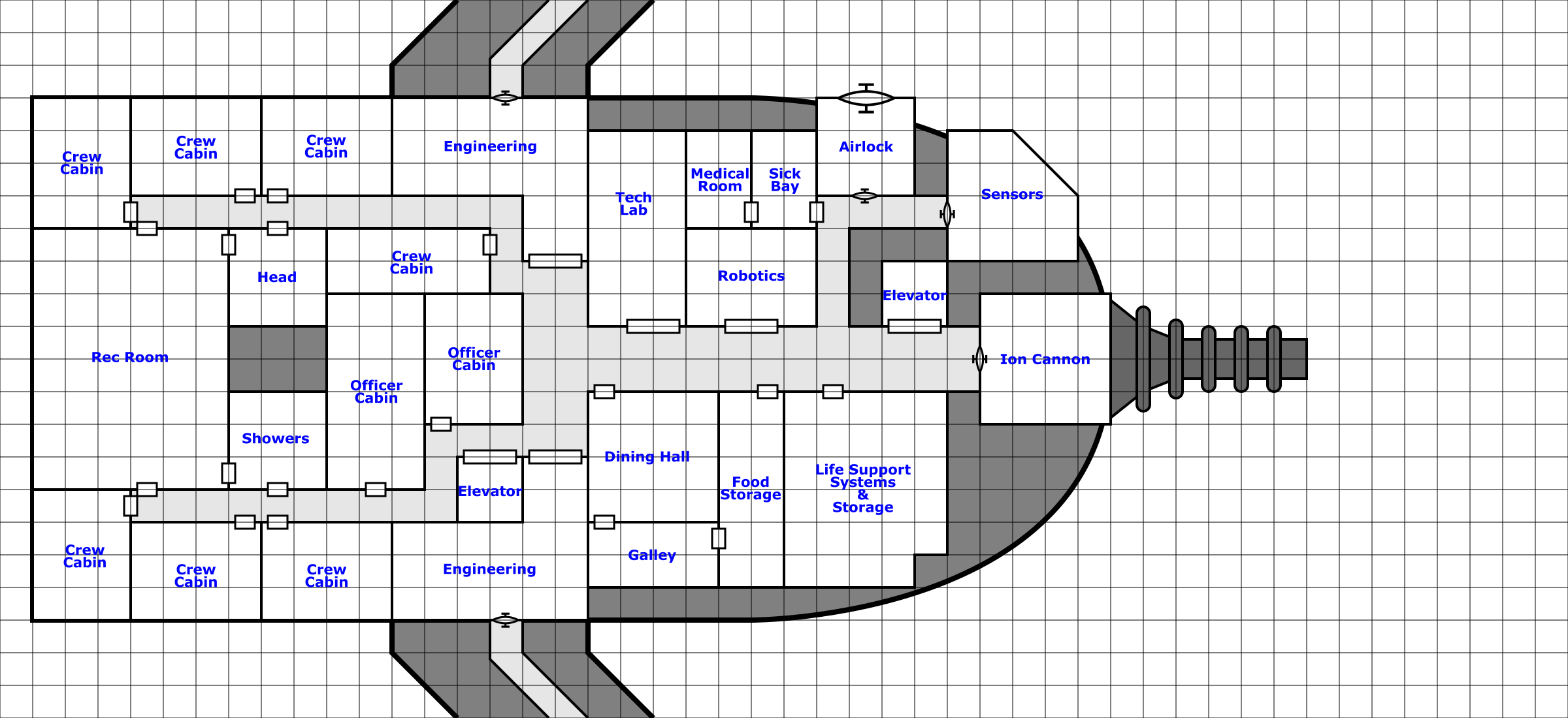
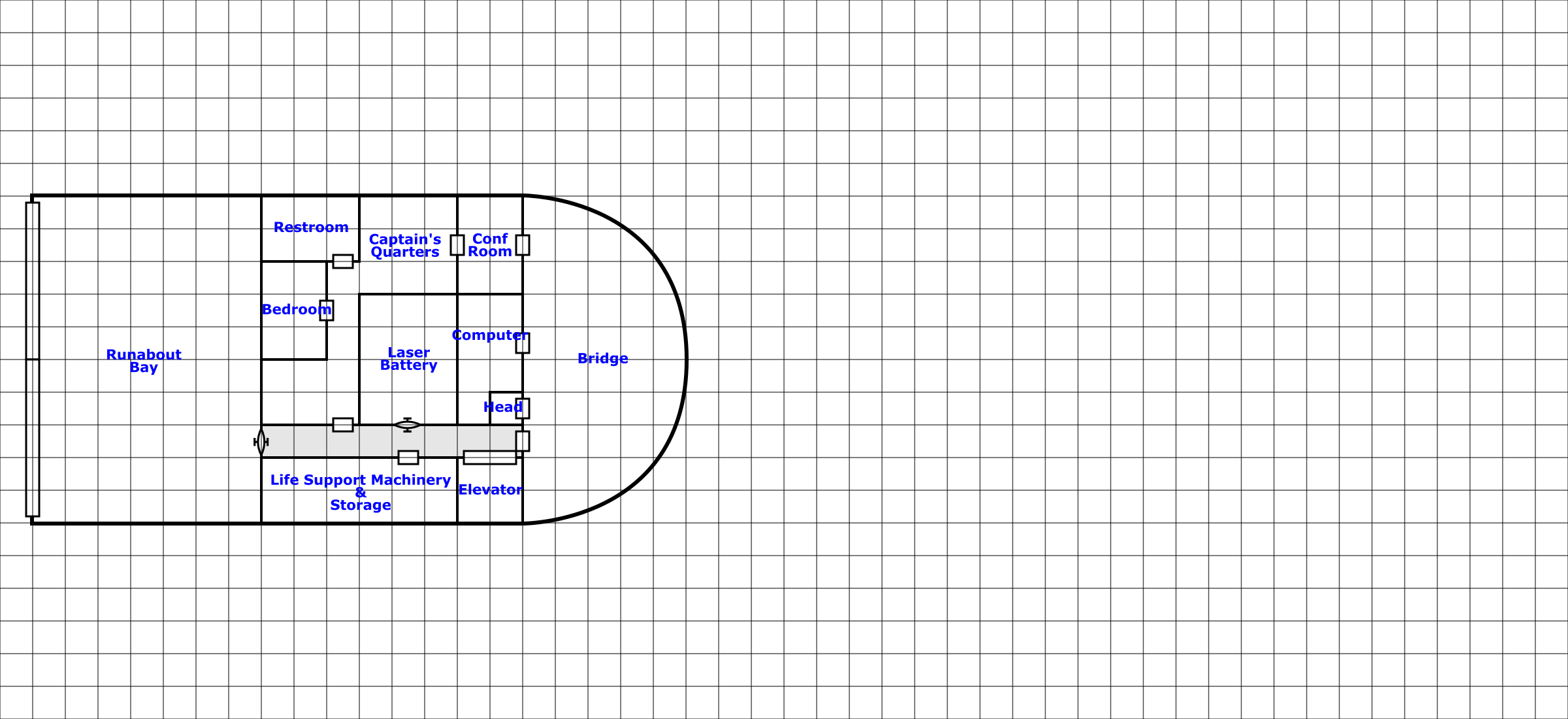
I’ve been working on the antagonist’s ship for the Ghost Ship Osiris module and now have the basic ship design down. This is a larger vessel, used by Thrawl and his scavenger crew to collect materials around the frontier and transport them for sale. It’s relatively well armed and with the larger crew, can even take on smaller vessels if it wants to. I still haven’t come up with an actual name for Thrawl’s specific instance of this ship but am simply calling the general ship type the Scavenger Transport. In this post I’ll talk about how I designed the ship.
It starts by deciding exactly the roll the ship is to play. I knew I wanted it to have a large cargo area, a bigger than normal crew (to provide muscle in scavenging operations), be relatively well armed, and relatively fast for a vessel of its size. The last bit is because in the module, it needs to be on par speed-wise with the PCs’ ship. And a fast, armed ship isn’t too bad for a crew that works a bit on the shady side of the law. Also the ship has to be able to carry a smaller personal runabout for the captain, again needed for plot reasons.
Given that basic plan, I sat down with the FrontierSpace rules and started picking out systems and features of the ship. Now to be honest, I had a bit of behind the scenes help as Bill has created a spreadsheet to use for basic ship design that helps a lot. That tool is not generally available but I believe Bill is working on a more detailed starship generation system that the basics provided in the core rules. In any case, I was able to determine all of the ships systems, components, and statistics using the spreadsheet. Using that information, I created a basic ship characteristic sheet.
There’s no picture of the ship yet as I haven’t completely designed it and don’t know what it looks like. But now that we have the specifications for the ship, we can start working on the deck plans.
Initial sketches
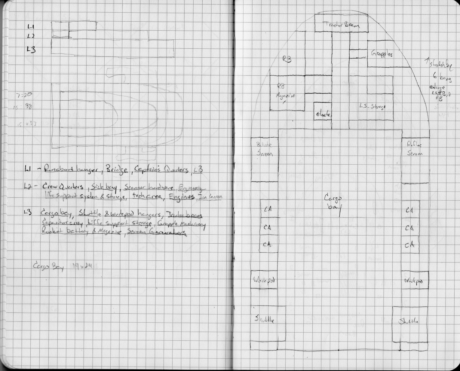
As I do with most of my ship designs, I start with paper and pencil. I have a nice little Moleskin graph paper notebook that I use to sketch out ideas and designs in so I started by drawing a side and top view of roughly what I wanted the ship to look like. It can be seen here in the upper left of this scan of two of the pages from the notebook (Note: on this an all other images in this post, you can click on them to get them at their full resolution).
Scan of two page of my design notebook showing the rough sketch of the ship (top and side views) plus whats on each deck (on the left) and the lower deck sketch on the right
The initial plan was to have three decks, each smaller than the one below forming a somewhat pyramidal or wedge shape. The larger box in the back that spans the upper two levels was to be the hangar for the runabout. The lower level would be taller than the other levels as it contains the cargo bay.
Once I had the basic outline, I started mapping out what I wanted each level to contain. I basically went through all the specifications and figured out which deck the machinery, storage, and hardware would be for each of those systems. You can see that list in the middle of the first page.
The basic breakdown was this:
Level 1 (bottom) – Cargo bay, shuttles and workpods, and many of the ship’s weapons and defenses along with other bulky systems such as life support and power storage.
Level 2 (middle) – Crew quarters and living space, sensors, ion cannon, engineering and tech spaces
Now that I had the basic plan, it was time to start getting into details. I started with the lower, largest level which can be seen on the second page of the scan above. On limitation of working in my notebook (which is 8.25×5 inches, 5 squares to the inch) is that there is only so much space to draw in. I probably should have sketched at 2m/square but did the sketch at 1m/square.
I stared by working out the cargo bay size. Assuming that one CU from the game rules is about a cubic meter, I figured out how big the cargo bay needed to be (see the notation on the left page) give that the bay itself was 6m in height. From there I started adding in the other features that were supposed to be on the ship.
After I finished this deck I compared it to the top view sketch that I created. I realized that the width matched pretty well assuming that the sketch was done at 3m/square except that the detailed sketch was 6m too short. So I made a note about that (on the upper right) to remind me to stretch it out a bit when I finally got down to drawing it. With the lower level done and an approximate scale, I started in on the next two levels.
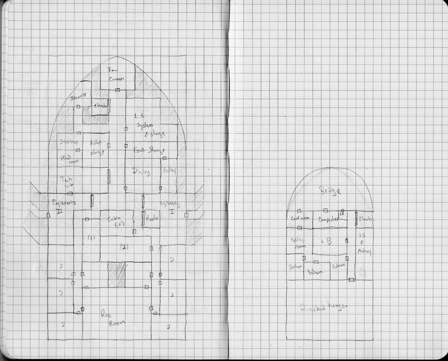
The middle (left) and upper (right) decks of the Scavenger Transport, to scale with the initial, lower deck
I actually skipped deck 2 to start and did the upper deck first. The reason for this is that I needed to know where the deck access would be so I could connect everything up. I knew I wanted the bridge at the front of the deck spanning the entire width and the runabout hanger at the back. The Laser Battery is actually mounted at the top of the ship so I put it in the center of the deck. I wanted a conference/meeting room off the bridge that was also connected to the captain’s suite. Picking the left side for the conference room determined where the Captain’s Suite would be. That put the elevator on the right and I added in the main computer, some life support space and small toilet off the bridge. This deck was done.
On deck two, I knew I wanted to put the crew cabins and living area in the back of the ship and the working areas center and forward. I actually started this level by putting in the two elevators (one to the deck below and one to the deck above) so I knew how the rest of the design had to work around them.
Next I added in the engineering spaces around where I wanted the engine access tunnels to be. Then came the location of the Ion Cannon (which extends out the front of this deck, not shown) at the front of the deck and then just started filling in details.
Also you might notice that I don’t have the roundabout hanger extending down into deck 2. It would have filled the space where the rec room is and a bit more. That was because as I was doing the sketches, I didn’t look back at my side view (the deck sketches were done several weeks after I made that side view sketch) and I completely forgot that that was my intention. So I decided to just extend it up more instead of down, making the ship even more pyramidal in shape.
Now, if you’re paying attention, you may have noticed that I forgot a fairly important feature that any good spaceship needs. (I probably forgot several but one is definitely going to be added in). Can you spot it? I’ll call it out when I get to drawing up the level it occurs on.
Slightly more detailed drawings
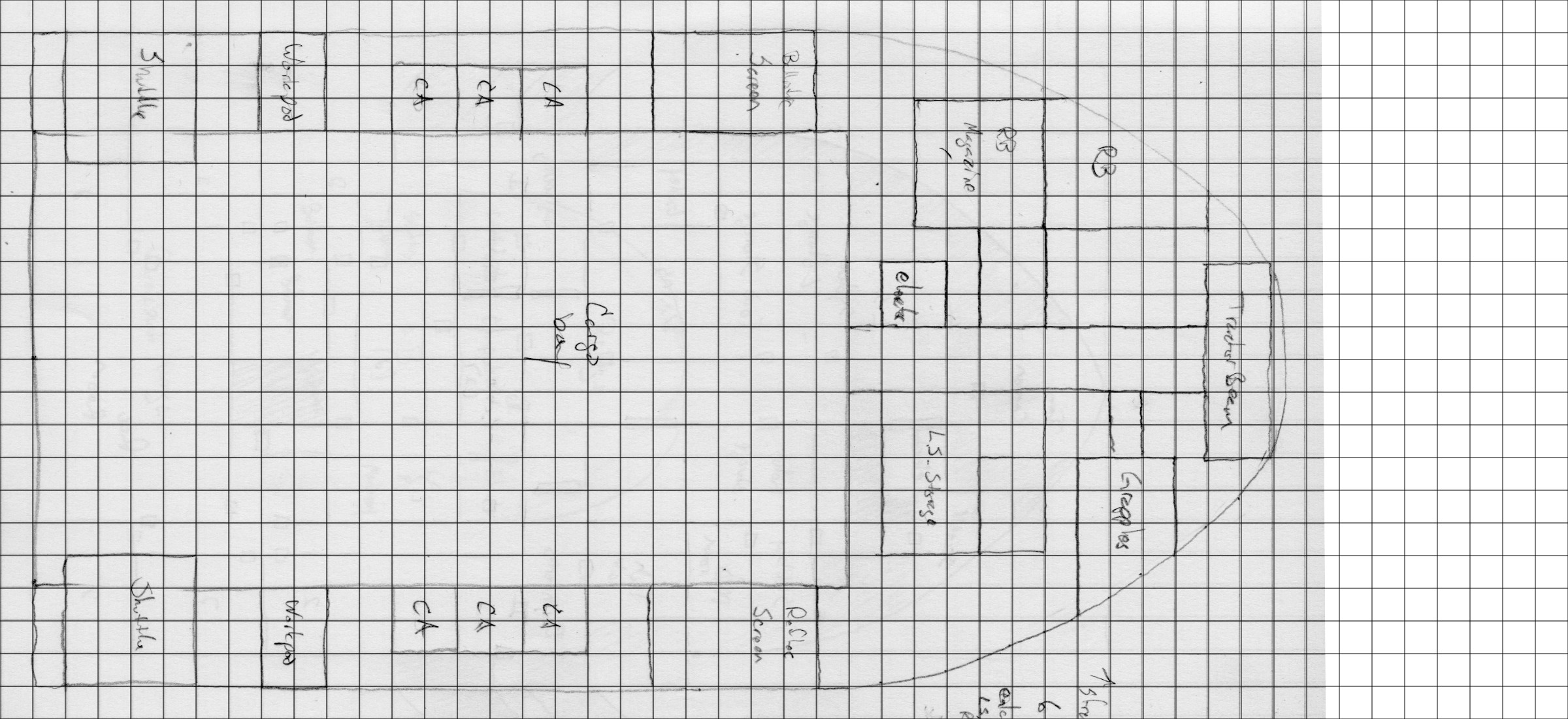
With the sketches done, it is time to start in on final drawings. I do my drawings in Inkscape and if these were going to be the final plans for this ship, they would end up with much more detail that you’ll see here. However, I knew that for this ship at least, I would be sending of the drawings to Bill to create the final version. The reason is that he has a specific style that he has used for ships in FrontierSpace that I can’t quite recreate yet. He had already done the PCs’ ship for this module in that style so I needed him to do the final drawings to match. More on this later. But that means that all I really need to do is get a good working drawing with the spaces mapped out for him to work from.
I like do do these drawings at 50 pixels per meter and 100 dpi. This is mainly due the fact that I started doing maps in Inkscape to digitally recreate some of the original Star Frontiers maps and those maps were all a two squares per inch. Give the preponderance of virtual table tops and the need for maps for those systems, I should probably shift to 70 pixels per square since that seems to be the default for those systems. However, since Inkscape is a vector drawing program, it’s really easy to scale the final map up (by 40%) to reach the desired scale. So I’ll probably stick with what I’m using since the math is easier.
Anyway, I start by laying down a grid. I know how big the ship is going to be so I create an image that is big enough to hold the ship plus 1 square larger on each side. Inkscape has a great extension to draw grids (Extension->Render->Grids->Cartesian Grid) so just use that to make the base grid:
Next I import the scans of my sketches and place them on a layer behind the grid. I have to rotate and scale the sketches so that they match the grid I just created. The sketch for the cargo deck looks like this:
You’ll notice that the sketch doesn’t go all the way to the end of the grid. Remember I said I needed to stretch it out? The final grid is larger than the sketch to accommodate that.
Next we lay in the outer hull. This is done on a separate layer. In the final drawings, the hull will probably have some final thickness and shape to it but for now, It’s just going to enclose the space where the rooms and passages will be. Some may stick out slightly but it provides the overall shape.
Starting a new layer, I turn off the gray fill on the hull (so I can see the sketch, I could also just play with the opacity if I wanted) and start drawing in the rooms and adding doors. Once that is all done, I turn the gray fill on the hull back on (I’ve also turned off the sketch in the background.)
Now, if I were working on the final versions, I’d next go in and add details to all the rooms: consoles, chairs, desks, beds, whatever the room required to show it’s use and function. However, as I’m just sketching out space, this is good enough for now. So we add some labels to indicate what the rooms are:
Now that deck one is finished, it’s time to do deck 2. This is where I realized I was missing something important. Besides the ship bays and the cargo doors, there’s no way to get in and out of the ship. I seem to have forgotten the airlock. Now originally I was going to just run a passage and airlock through the side of the ship near the dining room/galley in the space labeled food storage, but as I started drawing the plans I realized I had more room over by the sensors than I thought based on the sketch and was able to add it in there. The final deck two looks like this:
On this deck, the sensor and airlock extend outside the edges of the hull boundary I drew. This ship isn’t designed for atmospheric flight so that’s not a big deal. I also added in the barrel of the ion cannon I didn’t add in the engine areas, just a small passage headed out to them. The engine compartment will probably actually start right on the edge of this map or just off it. They aren’t all that far away from the ships.
From looking at these plans, you may have noticed that there seems to be an awful lot of life support and food storage space. That is intentional. If you look back at the ship stat sheet, you notice that it has expanded life support. The ship is designed to be able to spend a long time out in space without returning to port so it needs lots of space to store food, air, and water as it doesn’t have a complete recycling system, only a partial one.
Finally, the top deck. This one’s not that interesting, just a bunch of rooms with a small passage connecting them.
Finally we need a cross section view that shows how all these things are placed in relation to each other vertically. As I said before, the cargo bay and the runabout hangar are going to be taller than the rest of the rooms on the ship, each with a 6m tall ceiling (most of the rooms off the cargo bay will be this height as well). The other rooms are going to be 3m in height.
The other decision I had to make was how much space to place between the decks. When I’m building ships for Star Frontiers, I typically use 2m between decks. However, for this ship, I decided that the minimum spacing would be 1m (you’ll see why I say minimum in a minute). That gives room for piping, duct work, machinery and such between the levels. That’s also what that big 2x3m area in the middle of the living quarters section is for, to allow for connections between the lower and upper levels.
With that in mind, I drew a rough side view of the ship and placed the decks, elevator shafts and other bits in there relative positions:
You can see in the front of the ship, there is a lot of space between the lower deck and the deck above. That’s why the 1m was only a minimum. You can also see the laser battery there at the top. The outline of the ship at this point is really rough and I’ll updated it later once I have all the details.
Next Steps
With the basic plans done, I’ve sent them off to Bill to get the final treatment. He was quite excited to see the ship and get to work on the plans so hopefully I’ll have those back relatively soon. I’ll post them when he sends them to me. In case you haven’t seen his deck plan style, here’s the PCs’ ship from the game in Bill’s FrontierSpace style.
I now have the original drawing for this particular ship so I’ll be working in the future to be able to match it for future drawings.
My plan at this point is to start producing a 3D model of the ship. With the basic plans and design done, I can start working on a model that accurately reflects it’s shape. There will be a bit of back and forth between me and Bill as I work on this so that the outline on the deck plans and the model match. Expect the next big post in this series to be on the creation of that model. I’ve been working on brushing up my Blender skills as I’m going to attempt to create the model with that software instead of OpenSCAD which I’ve used for all my models in the past. I like the programmatic aspect of OpenSCAD but Blender provides much more flexibility. However, I might do a hybrid approach like I did with the Assault Scout model I used in the Assault Scout Technical Manual.
So there you go. A new ship. It can actually be used as is in your games if you want. Everything from here on out is details. Let me know if you have any questions, comments, or suggestions in the comment section below.
This post originally appeared on the now-defunct Arcane Game Lore blog.
My last post on Void Sickness along with reading Mike Bourke’s second portal article (I’m still a week behind but I’m catching up!), got me thinking about another aspect of Void travel that I like to use but which I don’t see talked that much about: where you come out on the other end. And since I’m approaching it as something you can’t completely control, the exact location is somewhat unpredictable and can have unexpected results. So this will be another entry into the November RPG Blog Carnival. Enjoy.
Never the Same Place Twice
Last time I played with the Disruption parameter. This time I want to talk about Repeatability. When I was defining void travel in the previous post, I stated that the repeatability was “vague” which was defined as “A new Portal from the same origin may be directable to some point near where the old one was” in the original portal article that sparked my first post. In his second article, he added, “but the exact same destination is unreachable” to the end of that when he summarized the detailed definitions. In that second post I liked the definition he gave for “unpredictable” which was “A new Portal from the same origin will connect with another point completely at random, uncontrollably, within the destination plane of existence, perhaps restricted to a significant region.”
My idea of void travel falls somewhere between those two. It’s not that reaching the exact same location is impossible, it’s just very unlikely. You’ll always end up close (on a cosmic scale) unless you make a major mistake but probably not in the same location. And in truth the chances of actually starting in the same place are slim to none as well depending on your definitions of location and the scale of what constitutes the “same origin” (Are you measuring in meters, kilometers, or AU?). Given the two summarized definitions I’m actually leaning a little more toward unpredictable but both work. The point is, the place you come out is always going to be different. Let’s look at that and what it may mean for your game.
Non-repeatability
So why is it not possible to come out in the same spot? From my perspective this comes down to two factors that related to how I treat void travel. In my interpretation of how void travel works, whatever vector you have in the real universe when you enter the void is the vector you maintain in the void. You can’t change your direction and you move in a “straight” line. Which means you need to be lined up exactly right or you’re going to go way off course.
Stay on Target
Just how exactly do you need to be lined up? Let’s look at a couple of examples. Take a piece of paper. Draw a small dot on it no larger than half a millimeter. Now hold that up at arm’s length. See how big that dot is? Depending on the size of your dot and the length of your arm, that dot covers an angle of about 2-3 arc minutes. If your direction vector were off by that much, how far off would you be at your destination?
I’m going to be generous and assume you drew a small dot and have a long arm and go with the 2 arc minute number. Assuming you make a small void jump, say 4.3 light years, the distance to the nearest solar type star, Alpha Centauri, you’d be off target by only 5.5 billion kilometers. Space is big, that’s not too bad, right? Well, that’s about 36.7 Astronomical Units (the distance between the Earth and the Sun). Which means if you were shooting for Earth, you’d be out by Pluto. Depending on how fast your ship is, that may take a while to compensate for.
But an error of 2 arc minutes is pretty big. We can do better than that. Let’s say we can get our error down to the size of an arc second (1 degree = 60 arc minutes = 3600 arc seconds). That’s equivalent to putting your dot about 24 feet (7.2m) away. If we do that and make the same jump to Alpha Centauri, we’d still be off by about 46 million kilometers or 0.3 AU, roughly the distance between the Earth and Venus at closest approach. (By the way, an error of 1 arc second means your ship moved laterally 4.8 mm after traveling 1 kilometer). And if you make a jump twice as far, the error will be twice as large as it is really just the direction error (in radians) multiplied by the distance traveled. Double the distance, double the offset.
Just based on that, you can see that you’re probably not going to come out at the same place at your destination no matter how hard you try. Getting your vector to that accuracy is going to take some effort. But there is another effect, the time spent in the void.
How Good is Your Clock?
The other aspect of determining your position is how long you spend in the void and how far you travel in a given amount of time. If there are errors in your time keeping, this will translate into errors in the distance traveled.
Let’s use the example I gave in my earlier post: void travel occurs at the rate of one light year per second. Now, a light year is 9.4607×10¹² km. That means that an error of a millisecond equal a distance of 9.4607×10⁹ km (63 AU, roughly twice the distance to Neptune). A microsecond error reduced that by a factor of 1000 and an error of only a nanosecond reduces that by another factor of 1000 or down to an error of only 9460.7 km, less than the diameter of the Earth.
Modern computers can get to about a 10 nanosecond resolution which means an accuracy of about 95,000 km roughly 1/4 the distance to the moon. Depending on the technology you allow in your setting (and what you allow to work in the void), the accuracy could be better or worse than this. But even with a microsecond error, the distance you’ll be off is only 0.063 AU.
So while there is an effect, and you probably won’t end up in the same spot, it is much less than the effect you can expect from an error in the velocity vector. Depending on the story you’re trying to tell, that may or may not be negligible.
Impact on Your Game
We’ve seen what the scale of the effect is, what impact does that have on your game? While the details will depend on you exact setting, here are three ideas off the top of my head.
Travel times
Given the natural variation in arrival locations, you are typically going to be off target which means the actual travel time to the destination is going to vary. It will no longer be “three days” but “three to four days”. You can’t really plan on exact time tables.
To put some numbers to that, assume you were off by the 0.3AU distance from earlier. Assuming your ship is traveling at 1% the speed of light (3,000 km/s, just under 11 million km per hour), it will take you about 4.25 hours to cover that extra distance. If you’re off by more or going slower, it will take even longer (and that’s ignoring a bunch of real world physics about changing direction and such which will only add to the time).
This means that you have to plan for and account for the extra time and it may add tension to a situation. We only have 100 hours to reach the destination and stop the “big event”. The jump and associated travel time takes 80+2d10 hours to just get to the location where the big event will happen. Do the characters arrive with hours to spare or are they landing with only minutes until they have to spring into action? What impacts will this have on their preparations? Will it limit what they can do or bring to bear in the situation?
Space Piracy
Again ignoring real world physics of matching velocities in space, the result of non-repeatability of void jumps means you’re probably not going to have space pirates lurking in the outer system for ships to appear and then pounce on them. Even if you had hundreds of ships entering a system every day, the odds of one appearing near where a pirate vessel was lurking is really, really small. The pirate ship could sit out there for years and never have an encounter. This means that piracy, if it occurs, will happen near the population centers, at remote, fixed outposts, or on the outbound leg of a journey before the void jump when the routes are much more predictable.
Arriving in Formation
Remember this scene from Return of the Jedi? (0:43-1:04 is the relevant part if you don’t want to watch the whole thing).
That just isn’t going to happen with void jumping. Even assuming that you can get the velocity vector the same for all the ships, which might be hard but could be possible (although not with everyone dodging in and out among each other like the fighters in the beginning of that clip) the timing variations between the ship computers will scatter everyone across tens of thousands of kilometers of space. You will need time to regroup. Which means you probably want to appear further out in the system to allow yourself that time which in turns means longer travel to your destination and a greater chance for discovery.
Or if you do allow for piracy to occur in the outer reaches of the system, merchants and their escorts may be separated on arrival. The convoy scattered across space. Can the escorts get back to their charges before the pirates attack or do they only arrive in time to extract revenge for damage done?
Void Travel is Unpredictable
From the above thoughts, it’s fairly obvious that this method of FTL travel has the potential to add some randomness and unpredictability into your game. Whether to add tension or just flavor, there is no real reason that void travel should be routine. Are there other ideas for impacts that come to mind because of the unpredictability? Let us know in the comments below.
Comments
Mike Bourke – November 24, 2015 at 11:28 am
There’s an obvious solution: the very short void jump. You arrive and find yourself 30 AU away from where you want to be? Jump for long enough to travel 29 AU. This distance is short enough that the final error will be relatively small.
Now, I happen to think that this tactic, while eminently sensible, is not as desirable as the additional flavor that the randomness gives. That leads me to suggesting that in order to make a jump, a ship has to utilize a minimum amount of power or more, which in turn means that there is a minimum jump distance.
This wouldn’t completely eliminate the viability of the tactic; it would mean that the most practical approach is to aim for a point half your anticipated error away from whatever the minimum jump distance is. For convenience, let’s say that your maximum error is 10AU per light year, and you are jumping 20 light-years, and that the minimum jump is 150 AU:
10 AU x 20 light years is 200 AU maximum error. Half that is 100 AU, so that’s the mean error that you will experience. But that leaves you too close to make the minimum jump, so you move that destination point out by the minimum, and aim to arrive 250 AU away. That means that your range of arrival points is 250±100 AU – so even if you get as close to your ultimate destination as possible, you are still a minimum jump away, and might be as much as 350AU.
The thing is that picking just any point that far away is not good enough; you would need some standard navigational reference points from which to get your precise distance for the second jump. Observations would take time, and without standard references, you might have to wait for weeks, months, or years for the objects you are measuring (presumably outer planets) to have moved enough to permit navigation.
And standard reference points for a jump means that your arrival point is a much smaller volume of space – making piracy possible after all. Not easy, but not entirely out of the question, either.
Mike Bourke – November 24, 2015 at 6:58 pm
Alternately, maybe a ship develops some sort of energy “charge” that simply delays making another jump for a period of time. That would prevent the “stop short and recalibrate” dodge – if there’s a deadline involved.
Tom – November 24, 2015 at 9:26 pm
Yes, both of those are possible implications as well. I like the minimum power required idea. I didn’t include it here but I also utilize limit on gravity wells. Kind of like Larry Niven’s hyperspace. You can’t get too close to a large mass and still have your void jump system work. This actually counter acts some of the implications depending on how you implement it. I think that will be another void jumping article at some point.
This post originally appeared on the now-defunct Arcane Game Lore blog.
I think it is safe to say that we can blame this upcoming series of posts on Delta from the Delta’s D&D Hotspot blog. In 2013 he did a series of posts every Saturday that was usually about my favorite game, Star Frontiers, which got me following his blog. Specifically, the impetus for this particular series of blog posts all started with his Forging Fighters series of posts (part 1, part 2, part 3) where he detailed the design and crafting of a fighter miniature for Star Frontiers, something that doesn’t exist in the miniature sets released by TSR all those years ago. I like those articles so much that with Delta’s permission, we reprinted his blog posts as an article in issue 7 of the Frontier Explorer.
At the same time, I had just discovered that the library at the university where my wife is an astronomy professor had acquired a 3D printer that was available for the public to use at minimal cost. And so I thought to myself, “I wonder if I could make 3D starship models that I could print?” At that time I was also working on my write-up of the Sathar Destroyer that would later be published in the Sathar Destroyer Technical Manual. So this naturally became the first miniature that I would attempt.
Fast forward about a year and now I work at the university library as the Physical and Mathematical Sciences Librarian (covering physics, astronomy, math, and computer science) in the very department that has the 3D printer. It’s literally around the corner from my office. That has made it very easy for me to use and test models on the printer. I’ve been having a blast. I’ve learned a lot along the way and thought that I should share my experiences in this series of blog posts.
The answer to the question of whether or not I could make models to print is a definite “Yes!” and I’ll be taking you through that journey. I’m up to 10 different models and will cover one or two of them in each post showing pictures of the model, the printed miniature, and is some cases, the final painted versions (I’m in the process of painting many of them right now).
Samples of the first 8 models printed and ready for painting
The picture at the right shows some of the first models printed and ready for painting. The one painted model is a prototype version of the Sathar Destroyer model that I printed and then painted as a test. Also pictured on the left are a lager version of the final destroyer model, the Sathar Heavy and Light Cruisers, more destroyers and some Sathar fighters. On the right we have a freighter, four UPF frigates, four Assault Scouts, and four pirate corvettes. Also pictured is a not to scale version of an exploration ship from a 3D model made by Jay Thruman. I’ll talk about all of these in future posts.
Software and Printer
As I was starting this process, I looked around for modeling software when I started this process, I was looking for something that was relatively simple to use and quick to learn. A lot of people use Blender but I’ve tried using it in the past and while quite powerful and versatile, the learning curve was just too steep for my tastes. In the end I settled on a program called OpenSCAD. It works much like a programming language in that instead of drawing and placing objects on the screen, you simply write a line or two of code telling the program what shape, how big, where, and how to rotate it. Then your code “compiles” into the 3D object. Being a programmer by profession and not any sort of an artist, this appealed to me immensely. There have definitely been some limitations and I think I’ll eventually have to change programs if I ever want to do anything besides the spaceships but it has served me well to date.
In addition to OpenSCAD for actually creating the models, I also use Autodesk’s Meshmixer to check the models and NetFabb’s cloud repair service (no defunct – link is to page on the Wayback Machine) to clean the models up. I’ve also used Inkscape to create a few shapes that I’ve then imported to use as parts of models. More about those in future articles as well.
The printer that I’ve been printing on is a Makerbot Replicator 2, printing at 200 micron (0.2mm) vertical resolution. I tried a few prints at the smaller 100 micron resolution but the printer just kept jamming. I’ll be talking about the joys and woes of using this printer as well. At the library we’re in the process of getting another printer or two of different brands and so when they arrive, I’ll also be talking about the differences and my experiences with the new printers.
Stay Tuned
That’s it for this introduction. I’ll be interspersing these modeling articles with my Designing Out Loud series in the coming weeks and months. It might be a little light on content over the next couple of weeks as we move through the holiday season but I’ll try to get something up each week. See you next time.